Results from Main web retrieved at 23:45 (GMT)
These are some useful packages for the laptops:
Development:
- subversion
- mercurial (hg)
- git
- texlive-full
- cmake
- build-essential
- opencv 2.0.0-4
- gdb
- gprofiler/etc
- ssh
Mobile Robots:
- Cyton (arm software) - http://robots.mobilerobots.com/wiki/Cyton_7DOF_Arm_Software

- Mobile Sim
- Aria
- ARNL
- GPS localization
- MobileEyes
- Joystick Driver, etc...
Player/Stage:
- this whole mess
ETC...
- Ogre ODE
- Blender
- RobotTestSuite
- boost libraries
My Links
- WelcomeGuest - starting points on TWiki
- TWikiUsersGuide - complete TWiki documentation, Quick Start to Reference
- Sandbox - try out TWiki on your own
- AlexCohenSandbox - just for me
My Personal Preferences
- Preference for the editor, default is the WYSIWYG editor. The options are raw, wysiwyg:
- Set EDITMETHOD = wysiwyg
- Fixed pulldown menu-bar, on or off. If off, the menu-bar hides automatically when scrolling.
- Set FIXEDTOPMENU = off
- Show tool-tip topic info on mouse-over of WikiWord links, on or off:
- Set LINKTOOLTIPINFO = off
- More preferences

 TWiki has system wide preferences settings defined in TWikiPreferences. You can customize preferences settings to your needs: To overload a system setting, (1) do a "raw view" on TWikiPreferences, (2) copy a
 Set VARIABLE = valuebullet, (3) do a "raw edit" of your user profile page, (4) add the bullet to the bullet list above, and (5) customize the value as needed. Make sure the settings render as real bullets (in "raw edit", a bullet requires 3 or 6 spaces before the asterisk).
Related Topics
- ChangePassword for changing your password
- ChangeEmailAddress for changing your email address
- UserList has a list of other TWiki users
- UserDocumentationCategory is a list of TWiki user documentation
- UserToolsCategory lists all TWiki user tools
 The following is an example of our light sensor working. Note how when a light sensor is given a light source, the contralateral wheels spin, meaning that the sensor not receiving light will turn towards where the source is.
» All Authenticated Users Group
This is a special group all authenticated users belong. The main use of this group is to lift a web level restriction at the topic level. This is close to AllUsersGroup. The difference is that unauthenticated users belong to AllUsersGroup but not to AllAuthUsersGroup. Let's say a web is viewable only by the members of the DarkSideGroup by the following line on WebPreferences.* Set ALLOWWEBVIEW = Main.DarkSideGroupBy putting the following line on a topic, you can make it viewable by anybody authenticated.
* Set ALLOWTOPICVIEW = Main.AllAuthUsersGroupThis topic is not necessary for the group to work because the group is implemented in the code instead of a topic that has members. Related topics: TWikiGroups, AllUsersGroup, TWikiAccessControl
» All Users Group
This is a special group literally all users belong. The main use of this group is to lift a web level restriction at the topic level. This is close to AllAuthUsersGroup. The difference is that unauthenticated users belong to AllUsersGroup but not to AllAuthUsersGroup. Let's say a web is viewable only by the members of the DarkSideGroup by the following line on WebPreferences.* Set ALLOWWEBVIEW = Main.DarkSideGroupBy putting the following line on a topic, you can make it viewable by anybody.
* Set ALLOWTOPICVIEW = Main.AllUsersGroupThis topic is not necessary for the group to work because the group is implemented in the code instead of a topic that has members. Related topics: TWikiGroups, AllAuthUsersGroup, TWikiAccessControl
My Links
- WelcomeGuest - starting points on TWiki
- TWikiUsersGuide - complete TWiki documentation, Quick Start to Reference
- Sandbox - try out TWiki on your own
- AnneMarieBogarSandbox - just for me
My Personal Preferences
- Preference for the editor, default is the WYSIWYG editor. The options are raw, wysiwyg:
- Set EDITMETHOD = wysiwyg
- Fixed pulldown menu-bar, on or off. If off, the menu-bar hides automatically when scrolling.
- Set FIXEDTOPMENU = off
- Show tool-tip topic info on mouse-over of WikiWord links, on or off:
- Set LINKTOOLTIPINFO = off
- More preferences TWiki has system wide preferences settings defined in TWikiPreferences. You can customize preferences settings to your needs: To overload a system setting, (1) do a "raw view" on TWikiPreferences, (2) copy a
Set VARIABLE = valuebullet, (3) do a "raw edit" of your user profile page, (4) add the bullet to the bullet list above, and (5) customize the value as needed. Make sure the settings render as real bullets (in "raw edit", a bullet requires 3 or 6 spaces before the asterisk).
Related Topics
- ChangePassword for changing your password
- ChangeEmailAddress for changing your email address
- UserList has a list of other TWiki users
- UserDocumentationCategory is a list of TWiki user documentation
- UserToolsCategory lists all TWiki user tools
My Links
- WelcomeGuest - starting points on TWiki
- TWikiUsersGuide - complete TWiki documentation, Quick Start to Reference
- Sandbox - try out TWiki on your own
- AnthonyWAScanSandbox - just for me
My Personal Preferences
- Preference for the editor, default is the WYSIWYG editor. The options are raw, wysiwyg:
- Set EDITMETHOD = wysiwyg
- Fixed pulldown menu-bar, on or off. If off, the menu-bar hides automatically when scrolling.
- Set FIXEDTOPMENU = off
- Show tool-tip topic info on mouse-over of WikiWord links, on or off:
- Set LINKTOOLTIPINFO = off
- More preferences TWiki has system wide preferences settings defined in TWikiPreferences. You can customize preferences settings to your needs: To overload a system setting, (1) do a "raw view" on TWikiPreferences, (2) copy a
Set VARIABLE = valuebullet, (3) do a "raw edit" of your user profile page, (4) add the bullet to the bullet list above, and (5) customize the value as needed. Make sure the settings render as real bullets (in "raw edit", a bullet requires 3 or 6 spaces before the asterisk).
Related Topics
- ChangePassword for changing your password
- ChangeEmailAddress for changing your email address
- UserList has a list of other TWiki users
- UserDocumentationCategory is a list of TWiki user documentation
- UserToolsCategory lists all TWiki user tools
My Links
- WelcomeGuest - starting points on TWiki
- TWikiUsersGuide - complete TWiki documentation, Quick Start to Reference
- Sandbox - try out TWiki on your own
- ArmandoCalifanoSandbox - just for me
My Personal Preferences
- Preference for the editor, default is the WYSIWYG editor. The options are raw, wysiwyg:
- Set EDITMETHOD = wysiwyg
- Fixed pulldown menu-bar, on or off. If off, the menu-bar hides automatically when scrolling.
- Set FIXEDTOPMENU = off
- Show tool-tip topic info on mouse-over of WikiWord links, on or off:
- Set LINKTOOLTIPINFO = off
- More preferences TWiki has system wide preferences settings defined in TWikiPreferences. You can customize preferences settings to your needs: To overload a system setting, (1) do a "raw view" on TWikiPreferences, (2) copy a
Set VARIABLE = valuebullet, (3) do a "raw edit" of your user profile page, (4) add the bullet to the bullet list above, and (5) customize the value as needed. Make sure the settings render as real bullets (in "raw edit", a bullet requires 3 or 6 spaces before the asterisk).
Related Topics
- ChangePassword for changing your password
- ChangeEmailAddress for changing your email address
- UserList has a list of other TWiki users
- UserDocumentationCategory is a list of TWiki user documentation
- UserToolsCategory lists all TWiki user tools
BumbleBee2 ROS Driver
The BB2 Driver uses package camera1394stereo, which System, Robotics, & Vision from the University of the Balearic Islands provided. We modified the sources files within the driver, which previously had issues with the queuing and dequeuing of the buffer ring probably due to the slow processor in the Pioneer 3AT robots we used. We modified it to single shot mode rather than continuous transmission. Using ROS, the program can load image data onto a server from the right and left stereo camera. Systems, Robotics, & Vision's Website: http://srv.uib.es/ SRV's Github: https://github.com/srv How to Run BB2 ROS Driver
- Server
- open terminal, run roscore
- Robot
- cd catkin_ws
- . devel/setup.bash
- cd src/camera1394stereo/launch
- export ROS_MASTER_URI=http://<server/laptop_ip_address>:11311
- export ROS_IP=<robot_ip_address>
- roslaunch stereo_camera.launch
- N.B: if there is an error with the guid, change both <guid>.ymal file name and the parameter in the <guid>.yaml file AND restart roscore
- After setup is complete, on the server (or laptop), run rosrun rviz rviz
- in RViz, click Add
- select Image
- within the Image parameter, change the Image Topic to either /stereo_camera/left/image_raw or /stereo_camera/right/image_raw
- a window should pop up with the received image being displayed from the stereo camera
Permissions
- Persons/group who can view/change the page:
- Set ALLOWTOPICCHANGE = FRCVRoboticsGroup
My Links
- WelcomeGuest - starting points on TWiki
- TWikiUsersGuide - complete TWiki documentation, Quick Start to Reference
- Sandbox - try out TWiki on your own
- BenBarriageSandbox - just for me
My Personal Preferences
- Preference for the editor, default is the WYSIWYG editor. The options are raw, wysiwyg:
- Set EDITMETHOD = wysiwyg
- Fixed pulldown menu-bar, on or off. If off, the menu-bar hides automatically when scrolling.
- Set FIXEDTOPMENU = off
- Show tool-tip topic info on mouse-over of WikiWord links, on or off:
- Set LINKTOOLTIPINFO = off
- More preferences TWiki has system wide preferences settings defined in TWikiPreferences. You can customize preferences settings to your needs: To overload a system setting, (1) do a "raw view" on TWikiPreferences, (2) copy a
Set VARIABLE = valuebullet, (3) do a "raw edit" of your user profile page, (4) add the bullet to the bullet list above, and (5) customize the value as needed. Make sure the settings render as real bullets (in "raw edit", a bullet requires 3 or 6 spaces before the asterisk).
Related Topics
- ChangePassword for changing your password
- ChangeEmailAddress for changing your email address
- UserList has a list of other TWiki users
- UserDocumentationCategory is a list of TWiki user documentation
- UserToolsCategory lists all TWiki user tools
Switches have been stacked, but management interface still considers them as two separate switches with the same IP
NOTE: 9/5/2010 Turning on the 2nd Switch causes the blades not to be able to communicate any longer, and the NICs on the machines flash green very rapidly
Labelled the cables in the following way:
ControllerNode: Main server with fiber connection is node "00"
Remaining servers each have 2 ethernet data ports denoted node / 1 and node / 2, where n is the servers 01 to 10
Top Port (eth1) is hotpluggable to an internet connection (X.X.X.142 on our local lab network)
Bottom Port (eth0) is set up as IP 10.10.10.1NODE, so IPs 100-110 are reserved for the Nodes
Both disks appear as one disk called: /dev/cciss/c0d0 to the operating system
SlaveNode Configuration:
Drives are configured as a logical volume via the HP Smart Array P400 RAID controller (Manual), RAID 0 ("fault tolerance")
Not sure what the other configuration settings are--ask Sirhan
Partition table of logical drive---must be connected using the RAID Controller (press F8 to get into it and set up the logical drives)
settings of logical drivess: Bays 1 and 2 or 3 and 4 (paired)
Clonezilla will refer to the drives
p1 1 2432 primary LINUX
p2 2433 7295 primary LINUX
p3 7296 10942 primary LINUX
p4 10943 end EXTENDED
p5 10943 17021 EXTENDED
63 sectors
121
594 cylinders
16065 * 512 = 8225280 bytes
-----
[original defaults read:
32 sectors
239389 cylinders 8160 * 612 = 4177920 bytes] ISSUES:
RAID controller doesn't like swapping of drives for Logical Volumes
NOTE ABOUT LOGICAL DRIVE MANAGEMENT:
If there are 2 logical volumes (4 drives) and bay 3 and 4 are removed, and replaced, the HP Smart Array controller will not detect ANY logical volumes, unless the old one is properly deleted before inserting new disks FAILED ATTEMPT TO CLONE:
/opt/drbl/sbin/ocs-onthefly -g auto -e1 auto -e2 -j2 -v -f sda -t sdb
dd if=/dev/sda of=/tmp/ocx
FRESH INSTALLATION ON A NODE:
1. SET UP THE RAID DISK ARRAY
- At the HP Smart Array P400 Controller Initialization screen, press F8 (it passes quickly so be ready)
2. I Installed the TESTING snapshot of Debian. I use the business card CD, install the base system, and only have the System Utilities and SSH server installed
3. configure /etc/hosts /etc/hostname /etc/network/interfaces appropriately (fill this in)
4. install the following package: openmpi-common openmpi-bin libopenmpi1.3 libopenmpi-dev emacs23-nox and openssh-server
5. I think something needs to be done with SWAP files
Currently Nodes 01-03 and 05-10 are set up with EXT4 + LVM + NFS, but this seems to fail with "scattertime" test (NFS hangs)
Node 04 is configured with ext3 + nfs and no LVM We noticed that ext4 + nfs + LVM was causing problems (the system was hanging), so we have gone back to the original partition table (above) with ext3 partitions. 9/7/2010 We also had an issue with the speed of the ethernet cards. Rather than running at gigabit speed (1000BaseT), it was running at 10BaseT half duplex. This was determined by examining /var/log/messages file or typing "dmesg" immediately after unplugging and replugging the cable back in. A simple reboot solved the problem, but we are unsure what set it to that mode in the first place. -- StephenFox - 2010-08-23
My Links
- WelcomeGuest - starting points on TWiki
- TWikiUsersGuide - complete TWiki documentation, Quick Start to Reference
- Sandbox - try out TWiki on your own
- BrunoVieiroSandbox - just for me
My Personal Preferences
- Preference for the editor, default is the WYSIWYG editor. The options are raw, wysiwyg:
- Set EDITMETHOD = wysiwyg
- Fixed pulldown menu-bar, on or off. If off, the menu-bar hides automatically when scrolling.
- Set FIXEDTOPMENU = off
- Show tool-tip topic info on mouse-over of WikiWord links, on or off:
- Set LINKTOOLTIPINFO = off
- More preferences TWiki has system wide preferences settings defined in TWikiPreferences. You can customize preferences settings to your needs: To overload a system setting, (1) do a "raw view" on TWikiPreferences, (2) copy a
Set VARIABLE = valuebullet, (3) do a "raw edit" of your user profile page, (4) add the bullet to the bullet list above, and (5) customize the value as needed. Make sure the settings render as real bullets (in "raw edit", a bullet requires 3 or 6 spaces before the asterisk).
Related Topics
- ChangePassword for changing your password
- ChangeEmailAddress for changing your email address
- UserList has a list of other TWiki users
- UserDocumentationCategory is a list of TWiki user documentation
- UserToolsCategory lists all TWiki user tools
TWikiGroups » CISDeptGroup
Use this group for access control of webs and topics.- Member list:
- Set GROUP = DamianLyons, RobertMoniot, ArtWerschulz, PhilipAmanqwaDanquah
- Persons/group who can change the list:
- Set ALLOWTOPICCHANGE = CISDeptGroup
Introduction to the Computing Facilities
of the Department of Computer and Information Sciences
at Fordham University
- Overview
- Computing facilities
- Logging in on Linux
- Logging in on Windows
- Backups: recovering lost files
- How to submit programming assignments
- Disk quotas
- File transfer
- Sending and reading email in Linux
- Using CTMC to describe the time steps of robot move
- Pick an expected value of initial time frame
- Reduce time for each step with decrease distance from Goal
-- (c) Fordham University Robotics and Computer Vision
Notes on filter_threshold
- Must have OpenCV 2.0 or a newer version installed.
- Result image is stored in a folder (locateed in same folder as the source) called test. Please create this folder before running the program.
- Adjust threshold values accordingly to filter the correct amount
- Also, adjust the erode parameters accordingly.
- Change threshold value accordingly: program will truncate everything in the image received from webcam except areas with threshold values between threshvalue and maxthresh.
- Source: filter_threshold.cpp: filter_threshold.cpp
- Makefile: Makefile: (works on ubuntu 11.10 and later versions.. for previous versions, replace LDLIBS with LDFLAGS).
 -- PremNirmal - 2011-08-23


ÿ
If we relax the assumption that cmap is bijective, then an input operation may have its port connected to several output ports. Dynamic fan-in and fan-out on ports is restricted to degree 1: this means that if an input port is connected to q output ports, this is just the same as q separate communication operations in sequence; if an output port is connected to q input ports, this is the same as q separate communication operations in sequence. Let (fan-out) FO(j,k) = { (i, a ) : cmap(i,a) =(j, port(j,k)) } and Let (fan-in) FI((i,k) = { (j, b ): cmap(i, port(i,k)) =(j,b) } where port(i,k) is the port used in operation IOi,k Case 2: cmap is irreflexive, respects processes, connections PS and is invertable with dynamic fan-in/out restricted to 1. For all processes i, IOi,top(i) there is at most one other process j, and IOj,top(j) such that cmap(i,port(top(i)))=(j,port(top(j))). Let fi(IOi,k) be the degree, number of different (j,b) for which cmap(i,port(i,k))= (j,b) Where port(i,k) is the port used in operation IOi,k Step 4 is modified since more than one (j, b ) could exist, however, with the assumption of dynamic fan-in/our restricted to degree one, there is at most one that is top(j) for some process j. The total number of IO operations is still n*m; however, on each operation we may need to search a fan-on FO(j,k) or fan-out FI(i,k) set. Since the largest that each such set could be is the maximum number of input or number of output ports, P = max(|IN|,|OU|), the worst case complexity would be P_*( _n*m/2).ÿ
If we relax the restriction on dynamic fan-in/out, then each time we encounter an operation in process i, with IOi,top(i) there will be in the worst case FI(i,top(i)) (and equivalently for fan-out) cases to consider. The problem is that selecting one of these cases may result in later being unable to match step 5 in the algorithm; therefore, all the different choices need to be explored to see if at least one allows all IO operations to be matched. Case 3: cmap is irreflexive, respects processes, connections PS and is invertable with no dynamic fan-in/out restriction, and all orderings of communications must be examined to determine if a) any order exists in which all IO operations are matched or b) amy order exists in which all IO operations are not matched. The maximum size of an FI or FO set is P and in the worst case all m IO operations will have this number of choices, resulting in an exponential complexity P(n*m)/2.IO operations composed with Parallel-min and Parallel-max compositions impose additional constraints on the IO matching process: Parallel-max: all the operations in composition must be matched, but they can be matched in any order. Parallel-min: any one operation in the composition can be matched, but not more than one. Case 4: cmap is irreflexive, respects processes, connections PS and is invertable with dynamic fan-in/out restriction of 1, and including parallel-min compositions. Parallel-min presents a choice at step 4 in the same manner that FI or FO would. However, in this case, as long as there is any match for step 5, it is sufficient. Since the number of choices available in the Parallel-min composition is still at most P, the complexity is not changed beyond P_*( _n*m/2). In fact, because the parallel-min includes P of the m IO operations, and because only one of these needs to be considered, it reduces the complexity to P*(n*(m-P))/2= P*(n*m/2) – P2*n/2.
Case 5: cmap is irreflexive, respects processes, connections PS and is invertable with dynamic fan-in/out restriction of 1, and including parallel-max compositions. Parallel-max also presents a choice at step 4 in the same manner that FI or FO would. However, all the m operations still need to be carried out, so there is no reduction in complexity as seen above. <meta name="robots" content="noindex" /> -- (c) Fordham University Robotics and Computer Vision
By 7th of June: Complete a working sample of sparse array code based on the proposal from last week. Will not implement all the features, but will storage of spare data using the proposed method. By 14th of June: Complete a working function of code that implements the full requirements specified in week1, including the ability to report and log the data structure size as sparse data is added. By 21st of June: Test the code and fix errors Integrate the code with the TimeDemo code for the information fusion display, and run the existing TimeDemo fusion algorithms showing data usage. By 28th of June: Continue to integrate the code with the TimeDemo code for the information fusion display, and run the existing TimeDemo fusion algorithms showing data usage and collection additional much larger data sets. By 5th of July: Fix all that needs to be fixed again.
- Requirements for a 3D sparse array data type: bullet list.
- Whether each of the STL container types would be useful for representing this (pros and cons maybe).
- Anything else you have found on sparse array representation that you want to share.
- Finishes with a proposal for how to proceed next week (ie base on a STL container class, build from scratch, using existing package from the web etc).
The program will be used to store the data the robots gather as coordinates. The robot goes through space and maps the surroundings, but most of those surroundings are empty space. A room for example is composed of 4 walls and some items but the rest is empty space. Storing the data for the empty space take a lot of unnecessary memory. That’s why we’re using a 3-dimensional sparse array to store the data, so that all the unregistered space doesn’t take up memory. Which STL container types would be useful for representing this? There are many container types that are not suited for the job because they focus more on insertion and extraction of data or have limited inserting options: Bitset, deque, list, queue, set, stack. The containers that would be suited are Array, Vector and Map. But since Array is defined memory and we don't know how much memory we will need, it is better to use Vectors. But Map is an even better option and we're considering using it as the container type for this program. -- (c) Fordham University Robotics and Computer Vision
COMPLETED
1. SPIE Defense and Security Symposium 2012, April 23-27 Baltimore MD; Abstract due Oct 10th 2011. Abstract Submitted. Accepted. Paper Submitted. Minor formatting request and resubmit. Presentation Made. 2. PerMIS'12 Performance Metrics for Intelligent Systems, March 20-22, 2102, College Pk. MD; Paper due date Nov 14th 2011, (http://www.nist.gov/el/isd/permis2012.cfm- Table of Contents of 2008 PerMIS Workshop. Includes all proceedings as pdf files.
- Table of Contents of 2009 PerMIS Workshop. Includes all proceedings as pdf files.
- 2010 PerMIS Workshop Schedule and proceedings. Does not include full proceedings.
IN PROGRESS
* IROS 2016 Deajeon Korea. Oct 9-14 2016. http://www.iros2016.org/FUTURE VENUES
* The 10th International Conference on Intelligent Unmanned Systems (ICIUS 2014) September 29 - October 1, 2014, Montreal, Quebec, Canada. *Deadline 5/1 * 23rd INTERNATIONAL CONFERENCE ON SYSTEMS ENGINEERING - ICSEng 2014 Las Vegas, USA, August 19-21, 2014. (http://www.icseng.com2011 -- (http://www.cs.utah.edu/events/conferences/cav2011
Page Permissions:
- Set ALLOWTOPICCHANGE = FRCVRoboticsGroup
12/19 10:00a, PI teleconf
JANUARY 2013 1/3 10:00am Group Teleconf
1/18 3pm DTRA PI Teleconf
1/31 1pm DTRA Group Teleconf *** RESCHEDULED
FEBRUARY 2/7 1pm EST DTRA Group Teleconf (Prem to join from CA 10amPST)
2/21 2pm DTRA PI
MARCH 3/7 2pm DTRA Group
Fordham visit to GATech, @CSER
Our presentation, evening 3/20;
Joint Project meeting 3/21 APRIL 4/3 11am DTRA PI
4/17 11am DTRA Group
MAY 5/1 DTRA PI
5/14 11am DTRA Group
5/28 4pm DTRA PI
JUNE 6/12 10am DTRA Group
6/25 1-3pm DTRA Webinar
JULY 7/8 1pm DTRA PI (Moved from 7/2 10am)
7/16 10am DTRA Group
Annual DTRA review, Arlington VA, 7/22-26
Congrats to James and Dagan for winning best Poster Award!!! AUGUST 8/13,14: Presentation to OSD PSC standing subcommittee on T&E, V&V
8/22,23: Presentations to United Technology Research Center
8/29 2pm DTRA Group
SEPTEMBER 9/11 DTRA PI 10am.
9/24 DTRA Group 1pm
OCTOBER 10/3 GT team arrives in evening, dinner in NYC.
10/4 Joint meeting in LC campus, finish mid afternoon.
10/14 DTRA PI 4pm.
SSRR 10/22-28
10/30 DTRA Group 11am.
NOVEMBER IROS 11/2-8
DECEMBER <meta name="robots" content="noindex" /> -- (c) Fordham University Robotics and Computer Vision
My Links
- WelcomeGuest - starting points on TWiki
- TWikiUsersGuide - complete TWiki documentation, Quick Start to Reference
- Sandbox - try out TWiki on your own
- DamianLyonsSandbox - just for me
My Personal Preferences
- Preference for the editor, default is the WYSIWYG editor. The options are raw, wysiwyg:
- Set EDITMETHOD = wysiwyg
- Fixed pulldown menu-bar, on or off. If off, the menu-bar hides automatically when scrolling.
- Set FIXEDTOPMENU = off
- Show tool-tip topic info on mouse-over of WikiWord links, on or off:
- Set LINKTOOLTIPINFO = off
- More preferences TWiki has system wide preferences settings defined in TWikiPreferences. You can customize preferences settings to your needs: To overload a system setting, (1) do a "raw view" on TWikiPreferences, (2) copy a
Set VARIABLE = valuebullet, (3) do a "raw edit" of your user profile page, (4) add the bullet to the bullet list above, and (5) customize the value as needed. Make sure the settings render as real bullets (in "raw edit", a bullet requires 3 or 6 spaces before the asterisk).
Related Topics
- ChangePassword for changing your password
- ChangeEmailAddress for changing your email address
- UserList has a list of other TWiki users
- UserDocumentationCategory is a list of TWiki user documentation
- UserToolsCategory lists all TWiki user tools
- Comment:
- My home page
- My Main activities
- Registration - become a <nop>TWiki user
- TWikiUsers - list of users of this <nop>TWiki site
- TWikiGroups - list of groups used for access control
%WLPARENT% Watchlist
Recent Changes
| Topic | Last Update |
|---|---|
| FRCVDataRepositoryHSVD2 in Main web | 2018-11-15 - 22:54 - r5 - DamianLyons |
Watched Topics


- To unwatch multiple topics, uncheck the topics, then click Update Watchlist.
- To watch all topics in a web, check the All checkbox, then click Update Watchlist.
- To have new topics added to your watchlist automatically, check the New checkbox, then click Update Watchlist.
- To add a topic to the list, visit it and click Watch on the menu bar.
Preferences
- Began software update for the robot, desktop and laptop
- Issued laptop 10 for testing, however, not all of the executables are currently working
- Bought hardware for the kinect
Adding a new n-ary operator, ie a function, to matheval
Example, lets add the 2-ary function tss_blah(a,b). Step 1: Edit scanner.l and add |tss_blah to the of the constants list. The '|' is the flex operator for OR, since constants is a list of possible names and it must separate the names. Step 2: Edit symbol_tableV.c and add "tss_blah" to the intialized list of names functions_2V_names tss_blah to the initialized list of functional pointers functions_2V (If you waated new 3-ary functions, add to functions_3V_names etc) Step 3: Put in an external declaration for the function in dlibinterface.h extern void *tss_blah(void *arg1, void *arg2) functions take and return data as void *, because there are many different types. They need to be cast at some point to the right type. You can directly add a C function to xmathV.c and xmathV.h if you want a local function. This is good for functions that calculate simplile stuff. However, if you need MOGS, c++ etc, then go to the nextstep Step 4: Only do this if you did not do a local function in xmathV.c, add to xmathV.h as well Make a function in dlibinterface.cpp that does the work you need done extern "C" void *tss_blah(void *a1, void *a2) { stuff in here } Step 5: Probably don't need to do this. It is the assumption that functions return reals. If you don't return a type real, then you may need to have the type of the return figured out. This is done in evaluate node in nodeV.c, under the 'f' switch case. For 1-ary and 2-ary functions, real is the only currently implementd case. For 3-ary functions, the type of the argumentsis used to decide on the type of the result. tss_condD(takes a real, a mog and a mog and returns a mog. tss_pdiff takes a mog, a mog and a real and returns a real. For 3-ary functions the variable argtypes_flag is used as a binary flag to remember the types of the arguments. Files change checklist: scanner.l, symbol_tableV.c, symbol_tableV.h, dlibinterface.h, dlibinterface.cpp, xmathV.c, xmathV.h <meta name="robots" content="noindex" /> -- (c) Fordham University Robotics and Computer VisionBackground
We considere a scenario where an autonomous platform that is searching an area for a target may observe unstable masonry or may need to travel over, by or through unstable rubble. One approach to allow the robot to safely navigate this challenge is to provide a general set of reactive behaviors that produce reasonable behavior under these uncertain and dynamic conditions. However, this approach may also produce behavior that works against the robots long-term goals, e.g., taking the quickest or safest route to a disaster victim or out of the building. In our work we investigate combining a behaviour-based approach with the Cognitive Robotics paradigm of rehearsal to produce a hybrid reactive-deliberative approach for this kind of scenario.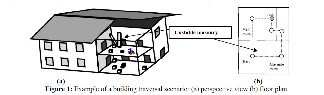 We propose an approach that leverages the state of the art in physics-engines for gaming so
that for a robot reasoning about what actions to take, perception itself becomes part of the problem solving process. A
physics-engine is used to numerically simulate outcomes of complex physical phenomena. The graphical image results
from the simulation are fused with the image information from robots visual sensing in a perceptual solution to the
prediction of expected situations.
Physics-engine software typically commits to a fairly standard taxonomy of object shapes and properties. To
avoid the issue of having a behaviour-based robot commit to or be limited by this exact same description of its
environment, we followed Macaluso and Chella (2007) in restricting the interaction between the simulation and robot to the
visual comparison of the output image from the simulation and the robots camera input image. This has the advantage of
keeping the robot control software and the simulation software quite separate (so it is easy to adopt new and better
physics-engine software as it becomes available). However, it also separates the two at a semantic level, so that the
robots understanding and representation of its environment can be quite different from that of the physics-engine.
Rather than looking for artificial landmarks to aid localization, as Macaluso and Chella did, our objective here is to
compare natural scene content between the real and synthetic images.
While fusing multiple real images poses some difficult challenges, fusing real and synthetic images posed a
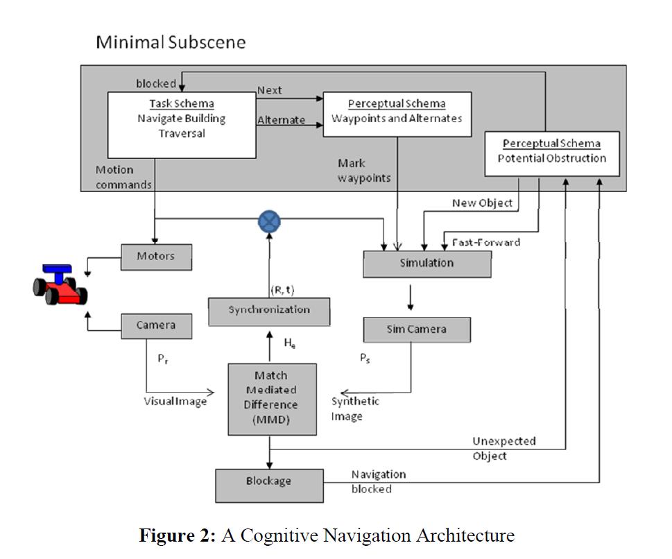
whole new set of problems. In Lyons et al. (2010) we introduced an approach, called the match-mediated difference (MMD), to
combining the information from real and synthetic images for static scenes containing real and/or simulated stationary
and moving objects. We leveraged Itti and Arbibs (2006) concept of the minimal subscene (developed for discourse
analysis) to capture how the robot modelled the scene being viewed, how it deployed the simulation and the MMD
operation to determine unexpected scene elements and how it requested and assimilated simulation predictions. The
minimal subscene contains a network of interconnected processes representing task and perceptual schemas (2003).
We propose an approach that leverages the state of the art in physics-engines for gaming so
that for a robot reasoning about what actions to take, perception itself becomes part of the problem solving process. A
physics-engine is used to numerically simulate outcomes of complex physical phenomena. The graphical image results
from the simulation are fused with the image information from robots visual sensing in a perceptual solution to the
prediction of expected situations.
Physics-engine software typically commits to a fairly standard taxonomy of object shapes and properties. To
avoid the issue of having a behaviour-based robot commit to or be limited by this exact same description of its
environment, we followed Macaluso and Chella (2007) in restricting the interaction between the simulation and robot to the
visual comparison of the output image from the simulation and the robots camera input image. This has the advantage of
keeping the robot control software and the simulation software quite separate (so it is easy to adopt new and better
physics-engine software as it becomes available). However, it also separates the two at a semantic level, so that the
robots understanding and representation of its environment can be quite different from that of the physics-engine.
Rather than looking for artificial landmarks to aid localization, as Macaluso and Chella did, our objective here is to
compare natural scene content between the real and synthetic images.
While fusing multiple real images poses some difficult challenges, fusing real and synthetic images posed a
whole new set of problems. In Lyons et al. (2010) we introduced an approach, called the match-mediated difference (MMD), to
combining the information from real and synthetic images for static scenes containing real and/or simulated stationary
and moving objects. We leveraged Itti and Arbibs (2006) concept of the minimal subscene (developed for discourse
analysis) to capture how the robot modelled the scene being viewed, how it deployed the simulation and the MMD
operation to determine unexpected scene elements and how it requested and assimilated simulation predictions. The
minimal subscene contains a network of interconnected processes representing task and perceptual schemas (2003).
Test World
A 15 room building was designed so as to present space for the robot to be confronted with challenges and be able to respond to the challenges by either continuing a traverse through the building or selecting an alternate path. Figure 7(a) shows the simulation model of the building from above. The entrance and exit doorways are on the bottom right and left. There are several large rooms with multiple doors which are the areas in which the robot can respond to challenges. There are also a number of smaller rooms which offer alternate routes through the building. Figure 7(b) shows the main waypoints (solid arrows) and alternate routes (dashed arrows). This information is stored in the waypoint schema.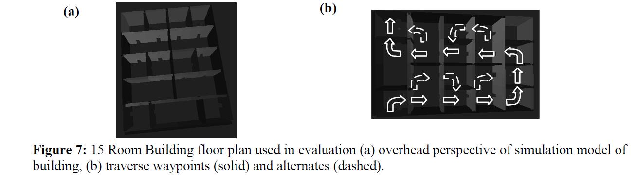 The robot makes the traverse of the building in either reactive mode (with the feedback from the simulation disengaged, so that no predictions are offered) or in cognitive mode (using predictions). For each run, the simulation building always appears the same. However, the real building can be altered dramatically as follows:
1. From one to four unstable columns of masonry can be placed as challenges, one in each of the large rooms.
2. The masonry can vary in color, in size and in initial velocity (how fast it falls).
3. The background wall colors can vary in color and texture.
The robot makes the traverse of the building in either reactive mode (with the feedback from the simulation disengaged, so that no predictions are offered) or in cognitive mode (using predictions). For each run, the simulation building always appears the same. However, the real building can be altered dramatically as follows:
1. From one to four unstable columns of masonry can be placed as challenges, one in each of the large rooms.
2. The masonry can vary in color, in size and in initial velocity (how fast it falls).
3. The background wall colors can vary in color and texture.
Videos!
- Small World Example: You will see the 'imagination' simulation screen on the upper left and the 'real' world on the bottom. There is a text screen on the right - you don't need to read that, its all diagnostics etc. In this example, you will see the robot navigate through the real world, its imagination following along, until it seems something unexpected - a block about to fall to block a door. You will see it being created in imagination, its effect simulated (and the 'real' world is stopped while this is shown to you -- otherwise it would be too fast to see), and detour taken because of the effect. The red sphere that appears in the 'imagination' marks where the robot is intending to move. This red marker makes it possible to do image processing to determine if a location is blocked or not (rather than 3D or sym bolic reasoning; faster!). cognitiveonly_smallbldg_1challenge.wmv.
- Reactive Only Example: You will see the real world on the top and the imagination on the bottom (no diagnostic screen for these longer runs). The aspect ratio is distorted, sorry. You will see the robot dash through the building and as it notices each falling block it tries to dodge it (using the Arkin (1998) potentiel field approach). Mostly it succeeds, but it depends on the size, shape and speed of the blocks of course - all randomly generated in these tests. In this run it makes it all the way to then end, and then gets clobbered! reactiveonly_4c_fail4.wmv.
- Cognitive Only Example: Different display again! The real world is bottom left; imagination bottom right and the diagnostic display is on the top. The comparison between real and expected scenes happens at every point, and when the falling block challenges are detected, you will see them recreated in simulation and their effect predicted. Of course it makes it to the end every time. cognitiveonly_text_4cs.wmv.
- Set ALLOWTOPICCHANGE = FRCVRoboticsGroup
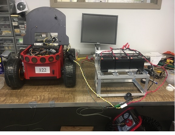
Battery Booster Pack for Mobile Robots P3-AT
Intro
This project started as a way to support the need for more power longevity during testing and as a way to utilize batteries several sizes too large that were accidently ordered. The batteries used for this pack were three 12V 12AH Lead Acid Casil Batteries about 4 by 6. While these batteries were several inches too large to fit in to the robot itself, the voltage and current were compatible enough that they could easily be added in parallel to the standard batteries used.
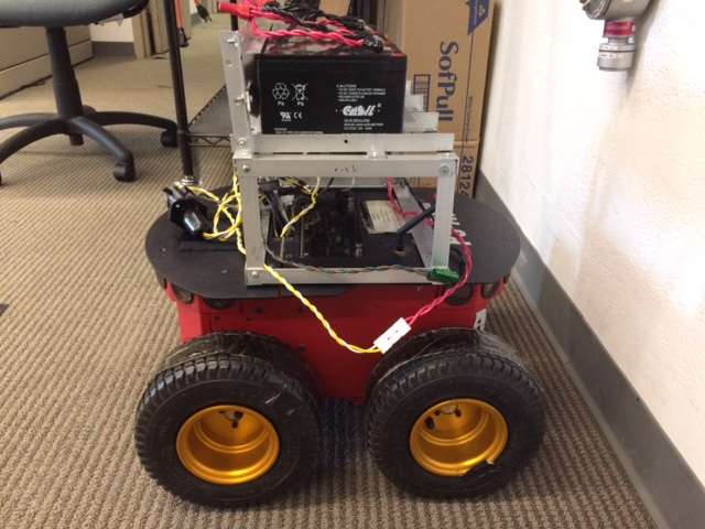
The Mount
In order for the batteries to be easily added to the bot without interfering with functionality or taking up the valuable real estate the top of the bot offers, a mount had to be constructed. For this mount we decided to use angle iron as the main material and nuts and bolts as the fasteners. These materials were chosen because of the ease with which they can be used for construction and the strength they'll provide in the face of the somewhat weighty batteries. The dimensions of the base are: 13.5" wide x 9.25" long x 5.5" tall. The battery rails are 7.25 long and 4apart with a flat bar attached underneath the rails for extra support.
The Wiring

 For the wiring we used two strands of size 8 electrical wire twisted together and soldered to bared female spade connectors, wrapped in electrical tape. Each section of wire was connected by wire nuts.
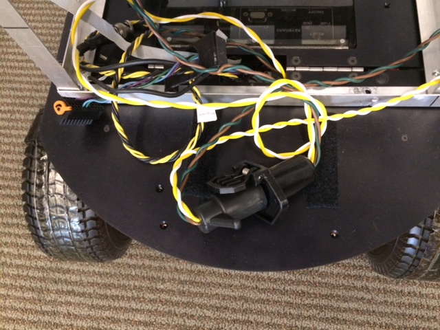
The connector we used between the batteries and the bot itself was a standard RV connector.
For the wiring we used two strands of size 8 electrical wire twisted together and soldered to bared female spade connectors, wrapped in electrical tape. Each section of wire was connected by wire nuts.
The connector we used between the batteries and the bot itself was a standard RV connector.
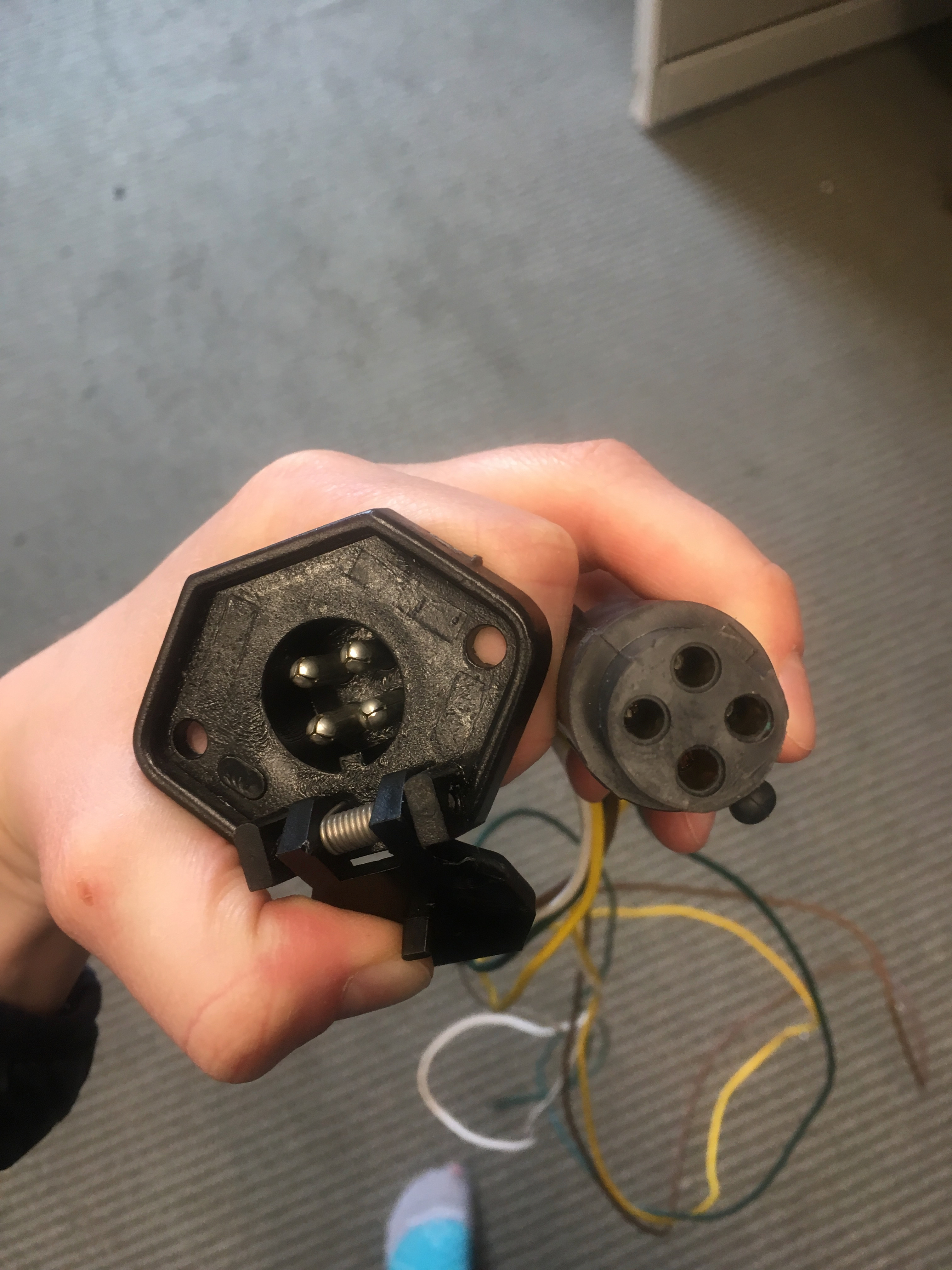 We cut the wires of the RV connector in the middle and connected the wires on the male end to the loose ends of the batteries wires with powerpole stackable connectors.

 In order to connect the wires stemming from the female end to the bot itself we bared the wires and crimped those on to ring tongue connectors which we then screwed in to a positive (pictured left) and negative (pictured right) connection on the robots battery strip.


The Entire Setup


Testing
This booster pack more than doubled the life span of the robot during two phases of testing. The first phase of testing consisted of infinitly looping through turns and direction changing. The robot was rasied on a box so that the teh wheels weer of the ground. Its left and right wheels moves in opposing directions for a set period of time and then changed directions until the battery was drained. Un-boosted the battery lasted about 4 hours, with the boosted the batteries lasted about 8 hours. There is some room for error as the the the length of the boosted bot's test run required it to be stopped, turned off, and restarted during lab occupancy intervals. The second phase of testing involved running a bot without the pack and bot with the booster pack in demo mode in an enclosed psace running object avoidance using the laser and sonar. The un boosted lasted roughly 2 hours while the boosted bot lasted roughly 4.5 hours. Video of testing can be found in the included attatchments below labeled: "Testing_of_Booster_Pack"Permissions
Persons/group who can view/change the page: REMOVE the first line to allow this topic to be seen by all- Set ALLOWTOPICCHANGE = FRCVRoboticsGroup
The FRCV Battery Booster for Pioneer 3AT Robots
This project started as a way to support the need for more power longevity during testing with the Pioneer 3AT robots. They are equipped with 3 12V batteries which on full charge will power about 60 to 90 minutes of robot activity at most. The 'add on' batteries used for this pack were three 12V 12AH Lead Acid Casil Batteries about 4 by 6. While these batteries were several inches too large to fit in to the robot itself, the voltage and current were compatible enough that they could easily be added in parallel to the standard batteries used. And they had a higher AH rating than the usual 12V robot batteries (7 to 9 AH). In order for the batteries to be easily added to the bot without interfering with functionality or taking up the valuable real estate the top of the bot offers, a mount had to be constructed. The connector we used between the batteries and the bot itself was a standard RV connector -- allowing for a quick connect/disconnect.
Permissions
- Persons/group who can view/change the page
- Set ALLOWTOPICCHANGE = FRCVRoboticsGroup
Stereo Server and Client
The stereoServer code is based on the Aria serverDemo/clientDemo code. Changes the the basic Aria code include 1. use of joystick is supported inclient demo. 2. multiple robots can be used 3. There is a single command to trigger a multi-pan or multi-tilt stereo scanClient code
The client code was modified from the Aria clientDemo in /usr/local/Aria/Arnetworking/examples/clientDemo.cpp The easiest way to compile this is to rename the original clientDemo.cpp and substitute this one, then use the makefile in /usr/local/Aria/Arnetworking/examples/ to make the executable. There are some different versions of this program. The principle difference is whether they support the multiple robot interface commands. Version 1.0 was an edit of the Aria clientDemo to support moving the robot with the joystick, and to send doStereoScan server command. To work correctly that needs to be connected to the stereoServer program, not the (Aria) serverDemo program. serverDemo will run okay under joystick control, but will ignore the new commands such as doStereoScan. Version 2.0 was modified to allow control of the DPPU pan and tilt angles during a scan by sending the doStereoPan and doStereoTilt and also to allow connection to multiple robots (instances of serverDemo or stereoServer). Commands were added to allow robot moves to be directed to each robot or broadcast to all robots. Because of network delays, broadasting to all robots does not mean they all move the same unfortunately. Version 3.0 added in support for control of the visual saliency architecture and automatic selection and data gathering motions for likely landmarks. This has to be run with the correct version of stereoServer to run the commands on the robot. Here is the joystick button mapping for V3.0 b1 - trigger, has to be pressed for motion to occur. b2 - do a stereoscan. b3 - broadcast robot commands. b4 - send to robot 0 only. b5 - send to robot 1 only. b8 - enable the saliency architecure on the next stereoscan. b9 - allow the robot to carry out an automatic saliency move. Here is the source of the latest version (v3):Server code
The server code is a heavily modified version of the serverDemo.cpp program in /usr/local/Aria/Arnetworking/examples. You need a new makefile to make it, you can't use the original from Aria, because of the dependence on the stereo camera (which is captured in the source file stereoCamera.[cpp,h]). There have been several version of the server code. The logfile that the server writes has the version number on the top. Version 1.0 was the modified (Aria) serverDemo.cpp program with support for the new server command doStereoScan. Version 2.0 added support for the doStereoPan and doStereoTilt (which had arguments, so more difficult) server commands. There output format was changed to write GPS data. But the GPS support code was probably not correct. Version 2.1. This version has support for older Aria that does not support GPS, and using serialGPS.cpp it writes GPS (north/west) and TCM2 (roll/pitch/compas/temp) data to the logfile for each stop. Version 2.2 has support for the saliency architecture, identifying salient landmarks and plotting either a confined space (corridors) or open space (room or outside) set of saliency actions to gather the landmark data. In addition to the stop log, there is now also a landmark log and a separate set of landmark datasets. If you are only interested in landmarks, you can just copy the landmark datasets, images and log. Here are the main sources file and the Makfile for the latest version:- stereoCamera.cpp: stereoCamera.cpp; interface to the BumbleBee
- stereoCamera.h: stereoCamera.h
- stereoServer.cpp: stereoServer.cpp
- checkSalience.cpp: checkSaliency.cpp; implements the saliency architecture
- landmarkList.h:landmarkList.h; support for manipulating lists of landmarks
- serialGPS.cpp: Read the GPS directly using serial port (because old Aria did not do this).
- Makefile: Makefile
register.cpp Notes and Instructions
Executable takes the log file as a command line argument. Assumes that PCL- Change the header in the pcd files from "rgb" to "rgba" (or modify rcv2pcd and reconvert your rcv point cloud files to pcd files with that header).
- Change the "PointXYZ" data type in register.cpp to "PointXYZRGBA"
- register.cpp
- CMakeLists.txt
- FindPCL.cmake
- Within that directory: mkdir build cd build cmake .. make register
- You need to convert the rcv point clouds to pcd. I downloaded all the rcv point clouds into a folder called "pointclouds_rcv". Using the bash script, I just tack on a ".pcd" to the txt filenames for simplicity, and the version of rcv2pcd I posted takes input and output filenames (I think I didn't change anything). Here's the bash script I used:
for i in pointclouds_rcv/* do
./rcv2pcd $i $i.pcd
done - Then move the log file and the executable into the folder with the pcd files. I had some issues with the 14th set of scans, so I just deleted them from the log file.
- Finally, it outputs to hallway.pcd. You can view this by: pcd_viewer hallway.pcd.
Image 1 (register.cpp v1): No pre-processing; only odometry estimates--ca. 1.8 million points

Image 2 (register.cpp v2): statistical removal and downsampling of each individual point cloud--ca. 1.4 million points
 hallway2_screenshots.tar.bz2
* Set ALLOWTOPICVIEW = FRCVRoboticsGroup
hallway2_screenshots.tar.bz2
* Set ALLOWTOPICVIEW = FRCVRoboticsGroup* Set ALLOWTOPICCHANGE = FRCVRoboticsGroup -- StephenFox - 2011-06-15
Effect of Field of View in Stereovision-based Visual Homing
D.M. Lyons, L. Del Signore, B. Barriage
Abstract
Navigation is challenging for an autonomous robot operating in an unstructured environment. Visual homing is a local navigation technique used to direct a robot to a previously seen location, and inspired by biological models. Most visual homing uses a panoramic camera. Prior work has shown that exploiting depth cues in homing from, e.g., a stereo-camera, leads to improved performance. However, many stereo-cameras have a limited field of view (FOV). We present a stereovision database methodology for visual homing. We use two databases we have collected, one indoor and one outdoor, to evaluate the effect of FOV on the performance of our homing with stereovision algorithm. Based on over 100,000 homing trials, we show that contrary to intuition, a panoramic field of view does not necessarily lead to the best performance, and we discuss the implications of this.Database Collection Methodology
The robot platform used by Nirmal & Lyons [1] was a Pioneer 3AT robot with Bumblebee2 stereo-camera mounted on a Pan-Tilt (PT) base. The same platform is used to collect stereo homing databases for this paper. As in prior work [2], a grid of squares is superimposed on the area to be recorded, and imagery is collected at each grid location. We need to collect a 360 deg FOV for the stereo data at each location. This will allow us to evaluate the benefit of FOVs from 66 deg up to 360 deg. The Bumblebee2 with 3.8 mm lens has a 66 deg horizontal FOV for each camera. The PT base is used to rotate the camera to construct a wide FOV composite stereo image. Nirmal & Lyons construct this image by simply concatenating adjacent (left camera) visual images and depth images into single composite visual and depth image.This is quicker than attempting to stitch the visual images and integrate the depth images, and Nirmal & Lyons note the overlap increases feature matching a positive effect for homing. The PT base is used to collect 10 visual and depth images at orientations 36 deg apart starting at 0 deg with respect to the X axis. The RH coordinate frame has the X axis along the direction in which the robot is facing, the Y pointing left, and is centered on the robot. The final angle requires the robot to be reoriented also due to pan limits on the PT unit. The overlap in horizontal FOV (HFOV) between adjacent images is approximately 50%. Each visual image is a 1024x768 8-bit gray level image, and each depth image is a listing of the (x, y, z) in robot-centered coordinates for each point in the 1024x768 for which stereo disparity can be calculated. The visual images and depth files are named for the orientation at which they were collected. The visual images are histogram equalized, and the stereo images statistically filtered, before being stored. The grid squares for a location are numbered in row-major order i in { 0, ..., nxn } with a folder SQUARE_i containing the 10 visual and 10 depth images for each. The resolution of the grid r is the actual grid square size in meters and is used to translate any position p = (x, y) in { (0,0), ..., ((n-1)r, (n-1)r) } to its grid coordinates and hence to a SQUARE_i folder. The orientation of the robot theta is used to determine which images to select. For example, in the Nirmal & Lyons HSV algorithm, at orientation theta, the image at (theta div 36)*36 is the center image, and two images clockwise (CW) and two counterclockwise (CCW) are concatenated into a 5 image wide composite image for homing. Of course the database can be used in other ways -- the images could be stitched into a panorama for example.Databases
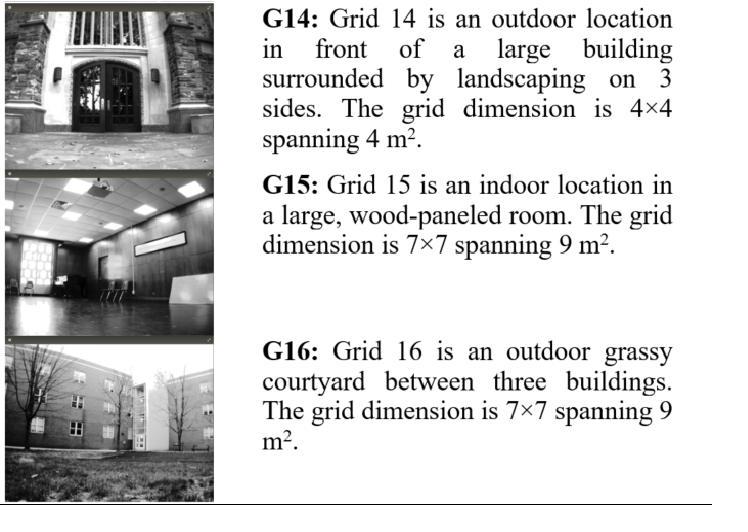
The results in this paper were produced with two stereo databases: one for an indoor, lab location (G11) and one for an outdoor location (G14). For both databases, r=0.5 m and n=4.
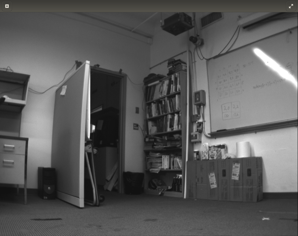
Figure 1: Grid 14 (left), Grid 11 (right), representative images
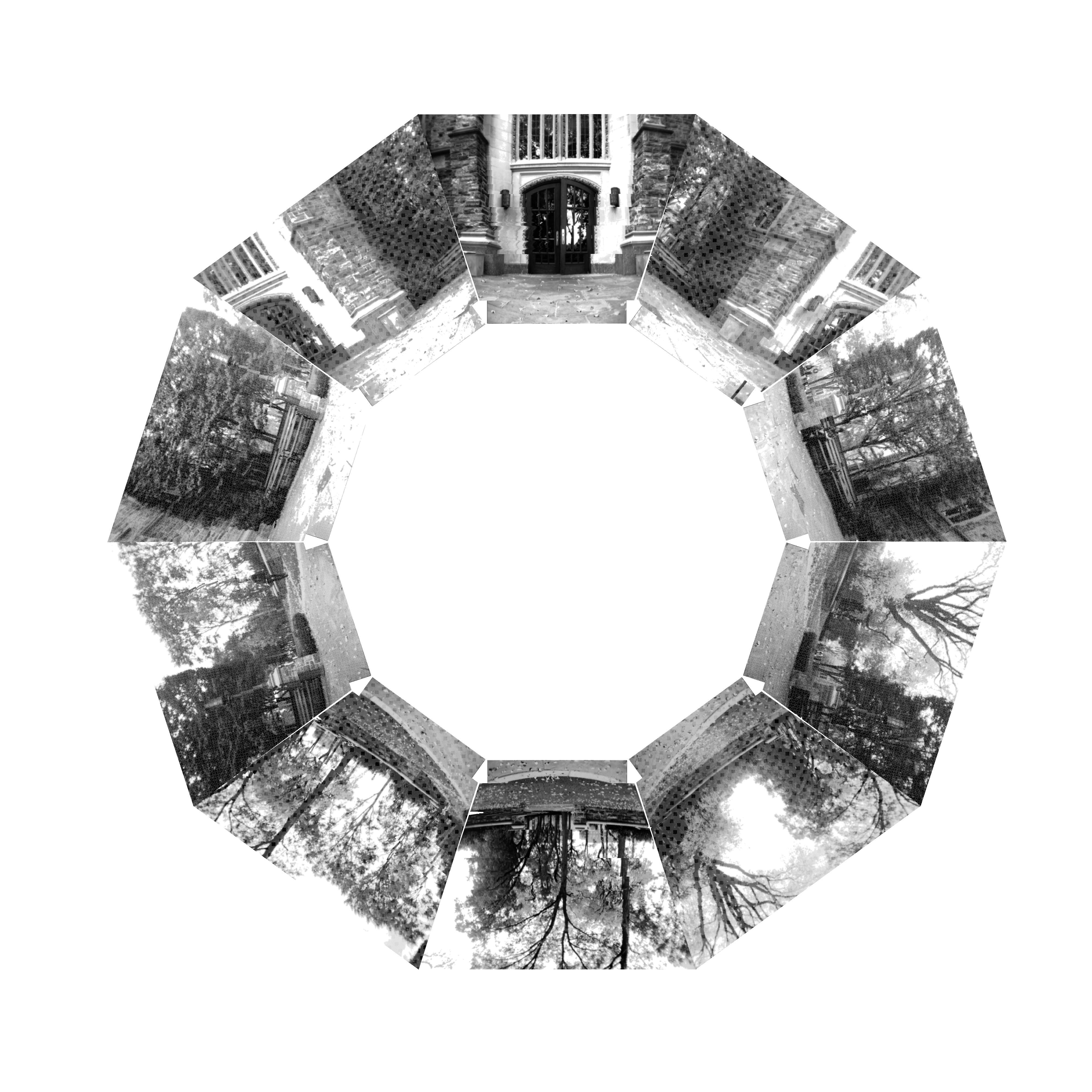
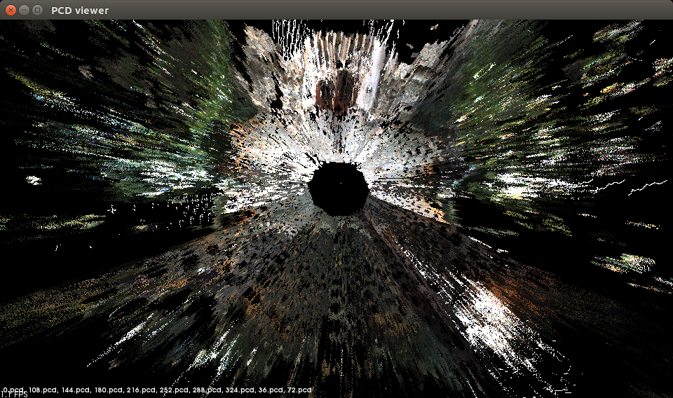
Figure 2: (a) Set of visual images displayed (keystone warped only for display purposes) at the orientation they were taken for a single square on the G14 database and (b) point cloud visualization of the stereo depth information for the same square.
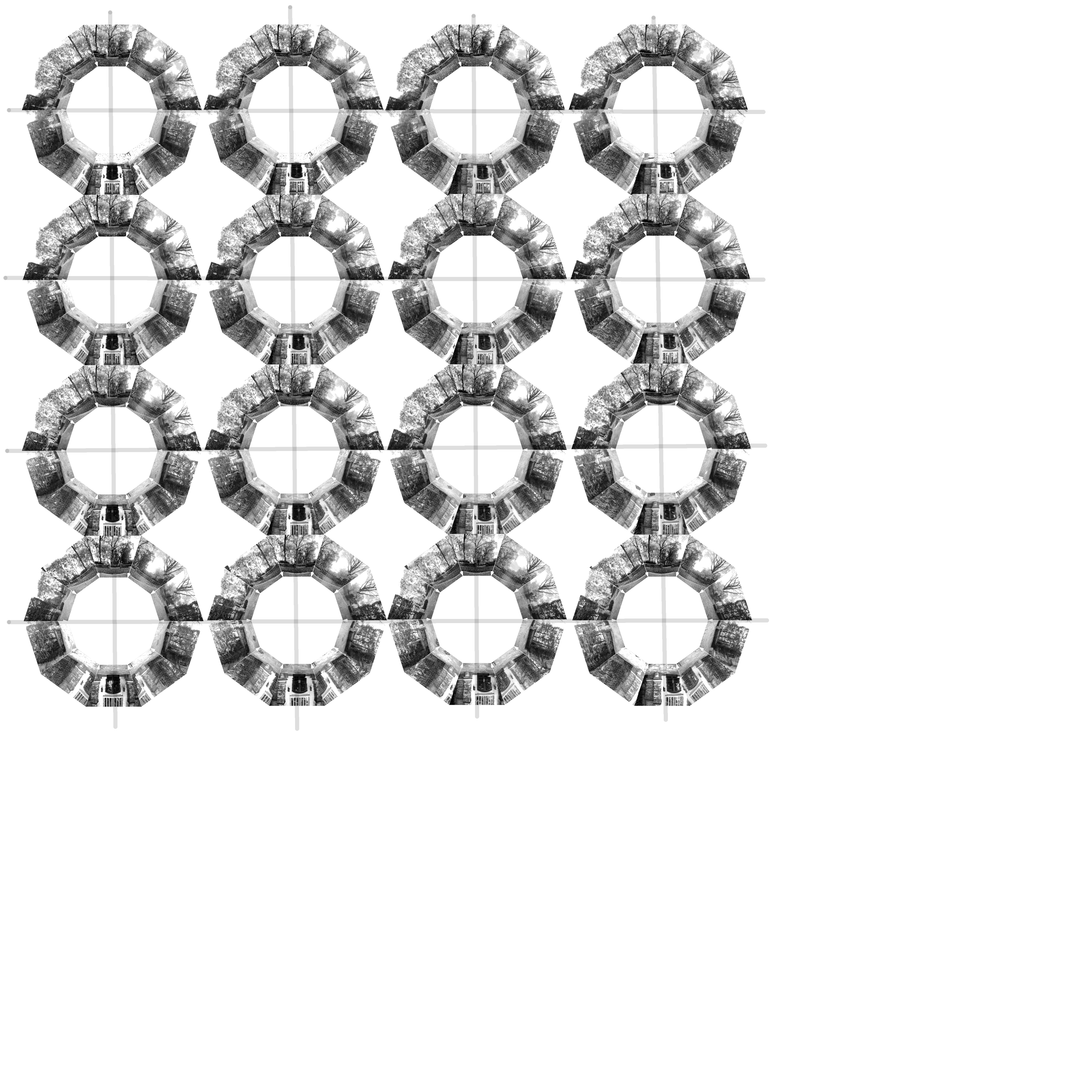
Figure 3: Grid of images for the G14 location. Each square shows the 10 visual images for that grid square in the same format as Figure 2(a).
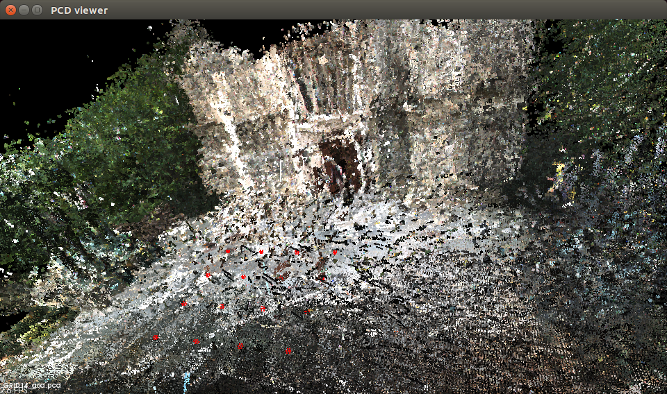
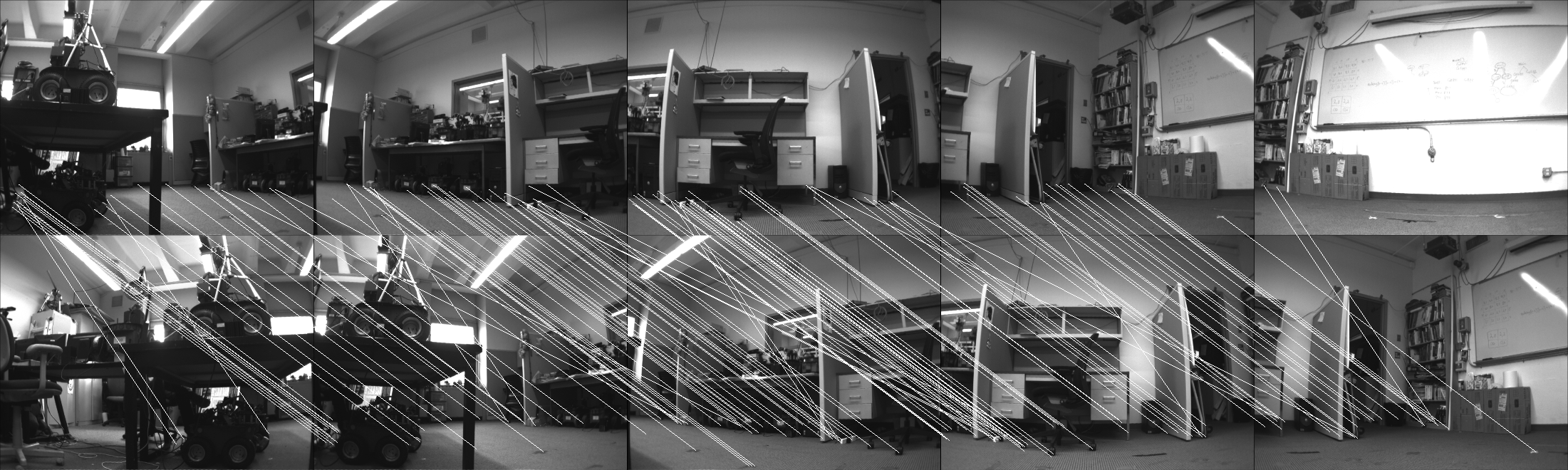
Figure 5: Wide field of view SIFT matching of home image (top) and current image (bottom) with lines between matched features (G11 database).
Repository Information
1. Files below labelled GRIDXX_grids contain visual image folders, while those labelled GRIDXX_cleanDump contain stereo depth data. 2. Histogram smoothing was performed on the visual images of GRID14, an outdoor grid, in order to compensate for lighting conditions. 3. A statistical filtering program, from the point cloud library, was executed on stereo-depth to clean up some stereo noise data. The parameters of the point cloud statistical filter were a meanK of 50 and a standard deviation threshold of 0.2.Datasets
* GRID11_cleanDump.tar.gz: Clean Data Dump folder for HSVD project. 11/7/16* GRID14_cleanDump.tar.gz: Clean Data Dump folder for HSVD project. 11/7/16
* GRID14_grids.tar.gz: Grid folder for HSVD project post smoothing. 12/5/16
* GRID11_grids.tar.gz: Grid folder for HSVD project. 2/23/17 This data is provided for general use without any warranty or support. Please send any email questions to dlyons@fordham.edu, bbarriage@fordham.edu, and ldelsignore@fordham.edu.
References
[1] P. Nirmal and D. Lyons, "Homing With Stereovision," Robotica , vol. 34, no. 12, 2015. [2] D. Churchill and A. Vardy, "An orientation invarient visual homing algorithm," Journal of Intelligent and Robotics Systems, vol. 17, no. 1, pp. 3-29, 2012.Permissions
* Persons/group who can change the page:* Set ALLOWTOPICCHANGE = FRCVRoboticsGroup -- (c) Fordham University Robotics and Computer Vision
The Evaluation of Field of View Width in Stereovision-based Visual Homing: Data repository
D.M. Lyons, B. Barriage, L. Del Signore,
Abstract of the paper
Visual homing is a bioinspired, local navigation technique used to direct a robot to a previously seen location by comparing the image of the original location with the current visual image. Prior work has shown that exploiting depth cues such as image scale or stereo-depth in homing leads to improved homing performance. In this paper, we present a stereovision database methodology for evaluating the performance of visual homing. We have collected six stereovision homing databases, three indoor and three outdoor. Results are presented for these databases to evaluate the effect of FOV on the performance of the Homing with Stereovision (HSV) algorithm. Based on over 350,000 homing trials, we show that, contrary to intuition, a panoramic field of view does not necessarily lead to the best performance and we discuss why this may be the case.Overview of the Data Repository
This web page is a repository for six stereovision visual homing database inspired by the panoramic image visual homing databases of Möller and others. Using these databases, we have conducted an evaluation of the effect of FOV on the performance of Nirmal & Lyons's HSV homing algorithm for a variety of visual homing missions in both indoor and outdoor situations totaling over 350,000 visual homing trials. The results indicate that while in general a wide FOV outperforms a narrower FOV, peak performance is not achieved by a panoramic FOV, and we discuss why that may be the case. This web is the data repository for the databases used in the paper. The six databases are briefly overviewed in Table 1 below. The picture to the left on each row is a single representative picture from the database.
Data Collection Procedure
A spatial grid is superimposed on the area to be recorded, and panoramic visual imagery is collected at each grid cell. The information is used as follows. A robot begins a simulation run with a home position grid cell and a start position grid cell. The visual information the robot receives is the stored imagery for the grid cell it occupies. A motion vector is calculated by comparing this imagery to the home grid cell imagery. This motion may move the robot to another grid cell, and the imagery comparison and motion calculation continues. Homing algorithms different in how these comparisons are done, how the motion vector is calculated, and how termination is decided. The robot used in our visual homing research is a Pioneer 3-AT robot with a Bumblebee2 stereo-camera mounted on a Pan-Tilt (PT) base. The Bumblebee2 with 3.8 mm lens has a 66 deg horizontal FOV for each camera. This limited FOV is one key challenge in building a visual homing database since each grid cell in the database must contain 360 deg of imagery; A robot can arrive at a grid location with any orientation and the simulation should be able to retrieve the imagery for that orientation. This issue is addressed by using the PT base to collect 10 visual and stereo depth images at orientations 36 deg apart, starting at 0 deg with respect to the X axis. The visual image stored is the left image from the stereo pair. The RH coordinate frame has the X axis along the direction in which the robot is facing, the Y pointing left, and is centered on the robot. The final angle requires the robot to be reoriented (in addition to the PT unit motion) due to PT unit pan limits.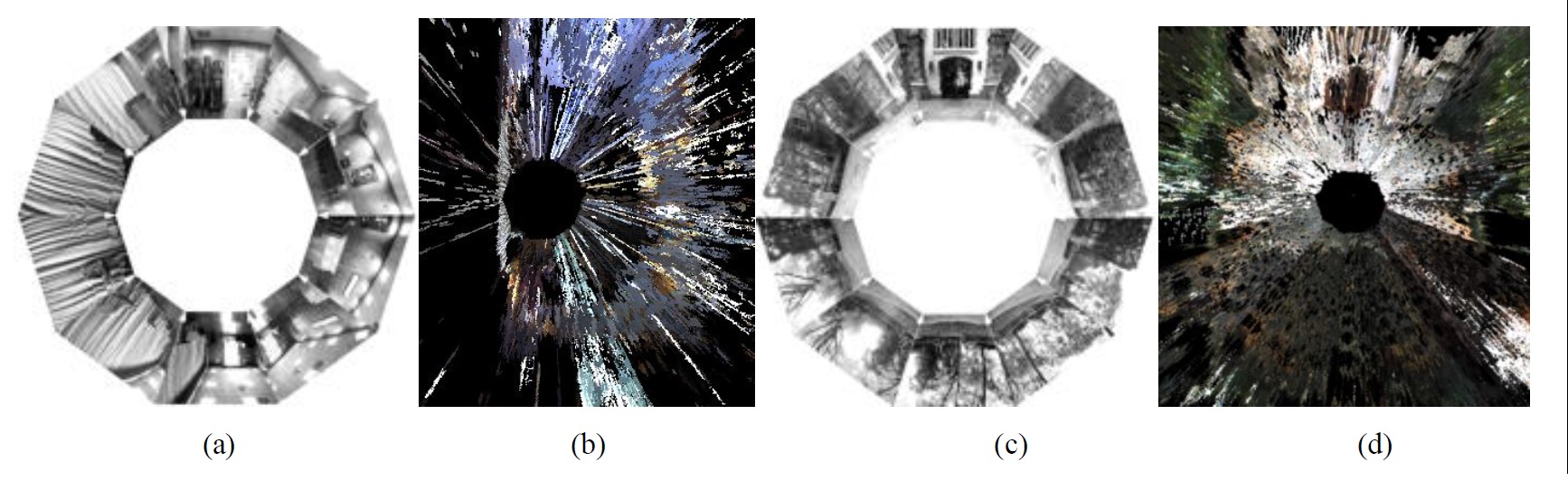
Figure 1: (a, c) Set of visual images (displayed keystone warped only for display purposes) for a single square on the G15 and G14 databases and (b, d) point cloud display of all the stereo depth information from directly overhead (the XY plane) for the same squares, respectively.
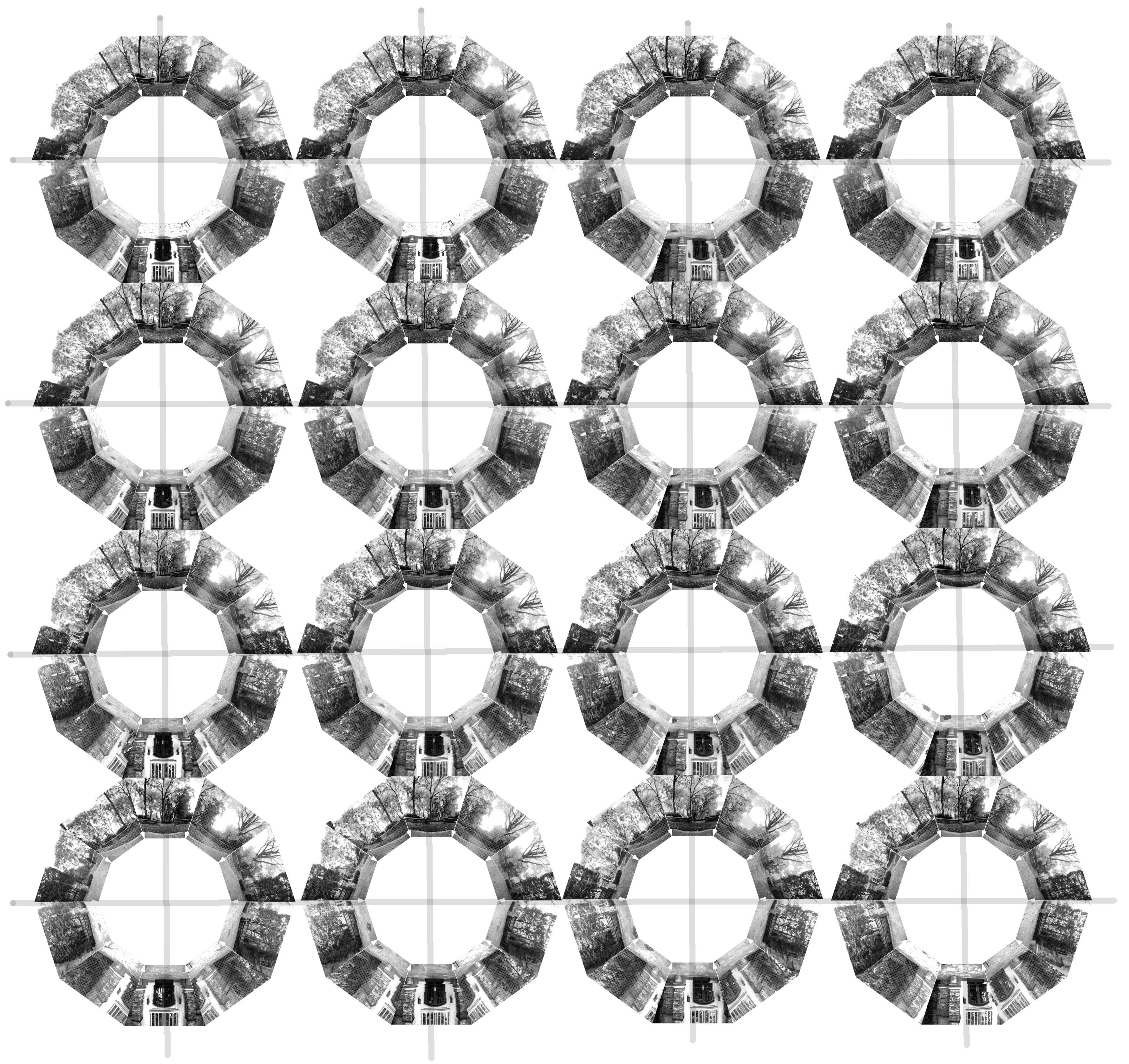

Figure 2: Grid of all 160 images for the G12 and G14 databases. Each grid cell shows the 10 visual images for that cell in the same format as Figure 1(a), and for each database the cells are arranged in the spatial order and orientation they were collected.
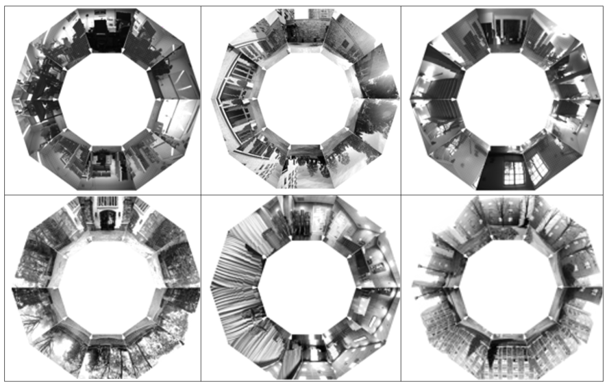
Figure 3: Set of all 10 visual images (displayed keystone warped only for display purposes) for a single cell from the G11 (top left) through G16 (bottom right)) databases respectively.
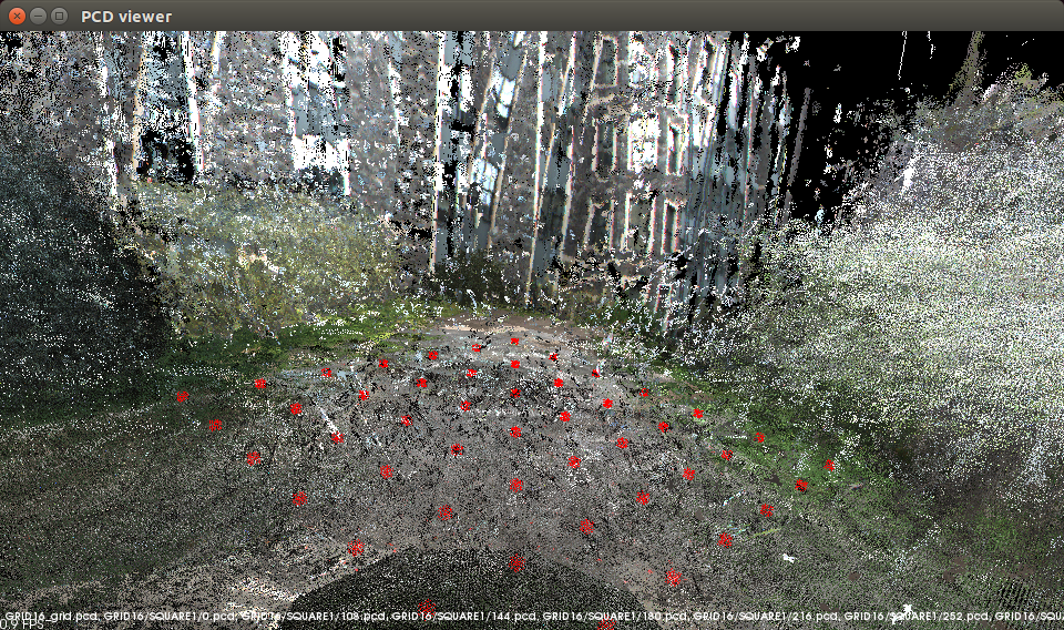
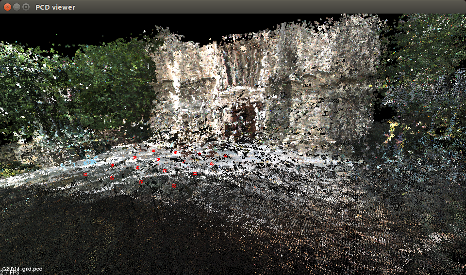
Figure 3.4: (left) A composite point cloud created from all 160 clouds (each in the form Figure 1(b)) of G14 and registered only using the spatial relationship of the grid; (right) shows this for the 490 clouds in G16. The grid of darker circles superimposed on the data in the foreground of each shows the grid vertices
A note on folder naming and orientation labeling orientation labeling
The depth files and the visual files are stored separately. For example, the depth files for G11 are stored in a folder called GRID11 with subfolders SQUARE1 through SQUARE16. The visual data for G11 is also stored in a folder called GRID11 with subfolders SQUARE1 through SQUARE16. So to download the the data, its best to make two folders Visual and Depth (for example) and download all the visual data to one and the depth to the others -- since the visual and depth folders for each database otherwise will have the same name! Each set of visual images for a cell is 7.5 MB in size and each set of depth images is 200 MB on average. In the Visual folder GRID11, subfolders SQUARE1 to SQUARE16, the images are labelled IMAGEnnn.pgm where nnn is 0, 36, 72, 108, 144, 180, 216, 252, 288, 324. These angles are with respect to the full positive pan angle, so 0 is actually 180 deg with respect to the X axis of the robot coordinate frame. In the Depth folder GRID11, subfolders SQUARE1 to SQUARE16, the images are labelled dataDump_nnn_mmm.txt and these are text files. Each line the text file has the entries:X,Y,Z are the 3D coordinates of the point with respect to the robot coordinate frame,
u,v are the image coordinates for the point (and used to register this point with the visual image)
d is the stereo disparity
r, g, b is the pixel color. The number is as follows: nn is 0, 36, 72, 108, 144, -144, -108, -72, -36 and where mm is 0 for all except one file which is nnn=-144 and mmm=-36 which marks the one rotation which the pan unit was at its max -144 and the robot based was rotated -36 to bring the robot to 180. The angle nnn in this case is with respect to the X axis of the robot coordinate frame. Its awkward that this is not the same labeling as for the visual data, and we will revise that in the next release. Histogram smoothing was performed on the visual images of all outdoor grids, in order to compensate for lighting conditions. A statistical filtering program, from the point cloud library, was executed on all stereo-depth files to clean up some stereo noise. The parameters of the point cloud statistical filter were a meanK of 50 and a standard deviation threshold of 0.2.
Datasets
The visual data
* grid11Image.tar.gz: Grid 11 4x4 grid image data.* grid12Image.tar.gz: Grid 12 4x4 grid, image data.
* grid13Image.tar.gz: Grid 13 4x4 grid, image data.
* grid14Image.tar.gz: Grid 14 4x4 grid, image data.
* grid15Image.tar.gz: Grid 14 7x7 grid, image data.
* grid16Image.tar.gz: Grid 16 7x7 grid, image data.
The depth data
* grid11Depth.tar.gz: Grid 11 4x4 grid depth data.* grid12Depth.tar.gz: Grid 12 4x4 grid, depth data.
* grid13Depth.tar.gz: Grid 13 4x4 grid, depth data.
* grid14Depth.tar.gz: Grid 14 4x4 grid, depth data.
* grid15Depth.tar.gz: Grid 14 7x7 grid, depth data.
* grid16Depth.tar.gz: Grid 16 7x7 grid, depth data. This data is provided for general use without any warranty or support. Please send any email questions to dlyons@fordham.edu, bbarriage@fordham.edu, and ldelsignore@fordham.edu. The short URL for this page is http://goo.gl/h3pU7Q
Permissions
* Persons/group who can change the page:<br /> * Set ALLOWTOPICCHANGE = FRCVRoboticsGroup -- (c) Fordham University Robotics and Computer Vision
| Evaluation of Field of View Width |
in Stereo-vision based Visual Homing
Overview
This dataset was collected by dml on 6-14-11 using the stereoServer and modified clientDemo software. Robot 116 was run around the U shaped 3rd floor of JMH.Procedure
Robot 116 Pioneer AT3 with Bumblebee stereo and DPPU pan-tilt was used to collected this dataset. The robot was equipped with onboard wireless AP to connected to control laptop running the modified clientDemo that speaks to stereoServer. StereoServer version V2 was used to control robot 116. The robot was positioned at the Robot Lab end of the U shaped 3rd floor of Building JMH facing down the corridor. Then stereoServer was started. The pan tilt scan parameters were set to do a pan scan of 20 deg, 0 degrees and -20 degrees at a fixed tilt of 5 degrees. Each set of 3 scans was repeated approx every 5 meters along the U shaped corridor until the robot reached the end. There were 15 stops (labelled 0 to 14) in all, and the sequence of 3 pan angles was scanned at each stop, producing 45 stereo datasets.Dataset
The dataset consists of The logfile which documents: the file name of the stereodataset, the (odometry) x,y,z,th and pan,tilt at which the dataset was taken.- run10839334_S0_S3.rar: run10839334_S3_S0.rar
- run10839334_S6_S4.rar: run10839334_S6_S4.rar
- run10839334_S10_S7.rar: run10839334_S10_S7.rar
- run10839334_S11_S14.rar: run10839334_S11_S14.rar
Fordham Robotics and Computer Vision Laboratory - Demos and Software
Rotational Legged Locomotion Pictures, Videos for novel triped robot. Robot "imagination" Pictures, Videos for using a 3D simulation to 'imagine' what might happen Terrain Spatiograms for Landmarks Pictures and code for generating unique 3D spatiogram views of landmarks from point cloud data. Instructions for Demo Step by step process of how to properly turn on robot, log into robot, and run demo files. Visual Homing using stereo-vision demo. Includes source code and instructions on how to run the demo. Old FRCV Lab Software and Demos pagePage protections
- Persons/group who can view/change the page:
- Set ALLOWTOPICCHANGE = FRCVRoboticsGroup
Major Equipment: The Robotics & Computer Vision Lab at Fordham includes the following major equipment:
RESOURCES: Fordham University, Robotics and Computer Vision Lab Laboratory: The Robotics & Computer Vision Laboratory is in the Department of Computer & Information Science in Fordham University. The Lab includes several computing stations and servers with high-powered GPUs, many robot platforms including ground robots and drones, moving and stationary camera systems and other infrastructure for development, maintenance and repair of the platforms. Computer: Fordham University has an extensive, multi-campus computing environment. The Department of Computer & Information Science has its own subnet connected to the main network. Department resources also span campuses and include multiple Windows and Linux workstations, six departmental servers, two HPC research clusters and full-time computing support staff. Major Equipment: The Robotics & Computer Vision Lab at Fordham is a large indoor lab (25 ×30) with multiple student working locations and which includes the following major equipment: Robots:- 5 Pioneer AT-3s with SICK laser, PTZ camera, compass, gyro, onboard computer with WiFi
- 6 Pioneer AT-3s with digital stereo-cameras on Pan-Tilt base, compass, gyro, onboard computer with WiFi
- 5 Pioneer AT-3s with PTZ camera, ea. With 5-DOF arm, compass, gyro, onboard computer with WiFi
- 1 Pioneer DX-2 with fixed stereo-camera
- >10 Crazyflie drones equipped with Flowdecks & Loco positioning system for drone localization
- 2 Parrot drones
- 6 ROS turtlebots (4 Burger Pi, 1 Burger, 1 Waffle Pi)
- Persons/group who can change the list:
- Set ALLOWTOPICCHANGE =FRCVLabGroup

Fordham Robotics & Computer Vision
Laboratory TWIKI
| Web | Description | Links |
|---|---|---|
| TWiki home with users and groups for access control | |
|
| TWiki documentation, welcome guest and user registration | |
|
| Sandbox web to experiment in an open hands-on area | |
|
| |
||
| Legend: |
|
Permissions
- Persons/group who can view/change the page:
- Set ALLOWTOPICCHANGE = FRCVRoboticsGroup
» FRCVLabGroup
Use this group for access control of webs and topics.- Member list:
- Set GROUP = TWikiAdminUser, DamianLyons, LabTech, MaggieGates
- Purpose of this group:
- Set DESCRIPTION =
- Persons/group who can change the list:
- Set ALLOWTOPICCHANGE = FRCVLabGroup
 MultiLingual Static Software Analyis
Our objective is to provide open-source tools that help analyze the way multilingual code interoperates to address security issues, software design and refactoring, efficiency and correctness. The first step is to create call graphs that represent the relationship between C/C++, Python, and JavaScript programs. The MultiLingual Static Software Analysis software tool (MLSA, pronounced Melissa for convenience) is a tool that analyzes software that is written in multiple languages and in which the languages call each other and produces a multi-lingual call graph.
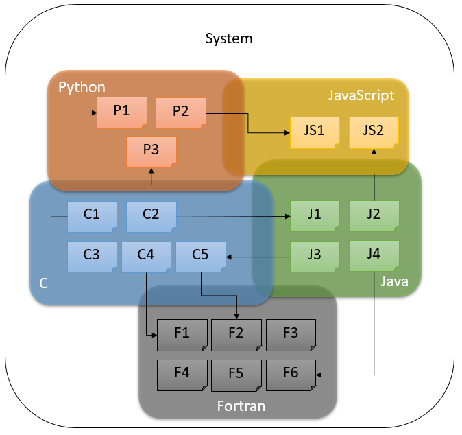
The MLSA software tool reviews function (procedure) calls within a set of source code files. It generates a call graph in csv/graphviz format with formatted information about function calls and their arguments and what files they are in. The tool is currently capable of analyzing programs in C/C++, Python and JavaScript, and in which a C/C++ program calls Python code through the python.h interface, a Python program calls C/C++ procedure using pybind11 interface, a Python program calls JavaScript code through PyV8 's eval function, or a JavaScript program calls Python code through JQuery's ajax command. The result in all cases is a call graph that includes procedures in all three languages showing their mutual call relationships. For more details, read on.
Background
Architecture
System Requirements
Installation
Execution
IG/repostats.py
IG/cFunCall2.py
Filters and Pipelines
Data Files
Status per Module
Known Issues for Version 0.1
Future Work
Ongoing Work
Permissions
Persons/group who can view/change the page:- Set ALLOWTOPICCHANGE = FRCVRoboticsGroup
- multilingual system:
 Background
Large software projects may typically have components written in different languages. Companies that have a large software codebase may face the issue of applying security, efficiency and quality metrics for a product spanning many languages. A developer or developer organization may choose one language for numerical computation and another for use interface implementation, or they may have inherited or be mandated to work with legacy code in one language while extending functionality with another. While there are many such drivers promoting multilingual codebases, they come with significant software engineering challenges. Although a software development environment might support multiple languages (e.g., Eclipse IDEs) it may leave the language boundaries - language interoperability - opaque. While it may be possible to automatically inspect individual language components of the codebase for software engineering metrics, it may be difficult or impossible to do this on a single accurate description of the complete multilingual codebase.
Heterogeneous or multilingual codebases arise in many cases because software has been developed over a long period by both in-house and external software developers. Libraries for numerical computation may have been constructed in FORTRAN, C and C++ for example, and front-end libraries may have been built in JavaScript.
A multilingual codebase gives rise to many software engineering issues, including:
- Redundancy, e.g., procedures in several different language libraries for the same functionality, necessitating refractoring
- Debugging complexity as languages interact with each other in unexpected ways
- Security issues relating to what information is exposed when one language procedure is called from another
Permissions
- Persons/group who can view/change the page:
- Set ALLOWTOPICCHANGE = FRCVRoboticsGroup
 Data Files
There are three kinds of data files in MLSA:
- data files that contain a monolingual Abstract Syntax Tree (AST) in text format
- data files the contain monolingual AST in JSON format
- data files in comma separated values format (CSV) that contain the results of various kinds of static analysis
- AST files: NAME.X_ast.txt or NAME.X_ast.json
- Monolingual procedure call graph files: NAME.X_call.csv
- Monolingual procesure call graph files with API integration: NAME.X_finalcall.csv
- Combined multilingual call graph file: NAME_callgraph.csv
- Combined function file: NAME_funcs.csv
- Forward flow control file: NAME.X_fcfg.csv
- Reverse flow control file: NAME.X_rcfg.csv
- Monoligual variable assignments: NAME.X_vars.csv
- Monolingual reaching definitions analysis: NAME.X_rda.csv
- NAME.X_call.csv
- call id, class, scope, function name, argument1, argument2...
- NAME.X_finalcall.csv
- call id, class name, scope, function called, argument1, argument2...
- NAME_callgraph.csv
- call program name, call program type, function program name, call id, class name, scope, function called, argument1, argument2...
- NAME_funcs.csv
- program name, class name, function name, number of parameters
Permissions
- Persons/group who can view/change the page:
- Set ALLOWTOPICCHANGE = FRCVRoboticsGroup
 Filters and Pipelines
AST file generation
- Clang-check is used to generate AST files for C and C++ programs
- The Python AST library is used to generate AST for Python programs
- SpiderMonkey is used to generate the AST for JavaScript programs
Monolingual procedure call filters
- cFunCall.py reads a NAMCE.c_ast.txt (or cpp) file and generates a NAME.c_call.csv file containing the function call information in the file, while also adding to a shared file NAME_funcs.csv that collects information about all the functions defined in the program.
- pyFunCall.py reads a NAME.py_ast.json file and generates a NAME.py_call.csv file containing the function call information in the file, while also adding to a shared file NAME_funcs.csv that collects information about all the functions defined in the program.
- jsFunCall.py reads a NAME.js_ast.json file and generates a NAME.js_call.csv file containing the function call information in the file, while also adding to a shared file NAME_funcs.csv that collects information about all the functions defined in the program.
Interoperability filters
- pyViaC.py reads a C function call file NAME.c_call.csv and scans for Python interoperability. Currently it only implements the Python.h PyRun _SimpleFile API. It ouputs a revised csv function call file NAME.c_finalcall.csv.
- jsViaPy.py reads a Python function call file NAME.py_call.csv and scans for JavaScript interoperability. Currently it only implements the PyV8 eval API. It outputs a revised csv function call file NAME.py_finalcall.csv.
- pyViaJs.py reads a JavaScript function call file NAME.js_call.csv and scans for Python interoperatbility. Currently it only implements the JQuerry ajax API. It outputs a revised csv function call file NAME.py_finalcall.csv.
Multilingual combination and graphin filters
- mergeFunCall.py merges the function calls in the XX_finalcall.csv files into a single function call file. It also finds the interoperability of python programs calling C/C++ procedures(pybind11). When called from mlcg.py, this output is given the name of the first argument to mlcg.py, e.g. if the argument was test0, then the file is called test0_callgraph.csv.
- Pybind11:
- MLSA processes all the call.csv files of the programs(C++, Python) and generates a merged csv file that shows the interoperability of programs by showing all function calls (shows where a function is defined and where is it called).
- In Python csvfile, it sees function calls , if it is of type 'A.B' it splits it and tries to find for a module/file named A and searches for the function definition in its csv file 'B' (using funcs.csv). It then adds the function call program name as 'A' and if the module appears to be a C++ file ,it tries to find if 'B' is present as the first argument of OBJ.def . If that is the case it replaces 'B' to the function name present in the second argument of OBJ.defin the csvfile.
- generateDOT.py produces a PDF file from a call graph csv file displaying the call graph.
Flow Control Filters
- cFlowControl.py reads an AST file NAME.c_ast.txt (or cpp) and generates a csv file containing the forward flow control information NAME.c_fcfg.csv, and reverse control flow information NAME.c_rcfg.csv.
- pyFlowControl.py - does not currently exist
- jsFlowControl.py - does not currently exist
Assignment collectors
- cAssignmentCollector.py reads the C AST file and locates all variable assignments and their line numbers. This provides an input that can be used in various kinds of assignment analysis. It is currently only used in the RDA analysis. It can currently also implement two simple static evaluation functions:
- It can report the assignment of a literal to a variable
- It can detect the use of strcpy in a C program to set a character array to a literal
- Anything else it marks as an expression or a function call
- pyAssignmentCollector.py - does not currently exist
- jsAssignmentCollector.py - does not currently exist
Reaching Definitions
- RDA (Kill-Gen/Exit-Entry) implements a reaching definitions analysis for each variable in the program. It reads the NAME.c_vars.csv file for the program to identify all variable assignments, and it reads the NAME.c_rcfg.csv file to get the reverse control flow for the program. It generates the file NAME.c_rda.csv with the solutions for the line entry sets. It doesnt record the exit set solutions, but it does derive them.
- cRDAGroup.py sets up the RDA pipeline of cAssignmentCollector, cFlowControl, and the RDA.
- pyRDAGroup.py - does not currently exist
- jsRDAGoup.py - does not currently exist
Pipelines
- cSA.py sets up the call graph and RDA pipeline for C/C++ sources
- pySA.py sets up the call graph pipeline for Python sources
- jsSA.py sets up the call graph pipeline for JavaScript sources
- mlcg.py processes its argument list of files and folders, calling cSA, pySA, jsSA as necessary to product a combined multilingual call graph.
Permissions
- Persons/group who can view/change the page:
- Set ALLOWTOPICCHANGE = FRCVRoboticsGroup
 Architecture
Lightweight program (which we call filters) operate on program source files and/or data files and produce data files. The filters can be stacked in pipelines, where each filter in the pipeline reads data files generated by prior filters and in turn generates new data files. The design motivation behind this structure is to allow pipelines of filter programs to be constructed to implement program analysis. This modular design is important to isolate the language-specific first pipeline stages from later language-independent modules and in this way support sophisticated analysis for multilingual codebases.

 The process starts with C, Python and JavaScript source code from which separate ASTs (Abstract Syntax Tree) are dumped using Clang-Check (for C files)
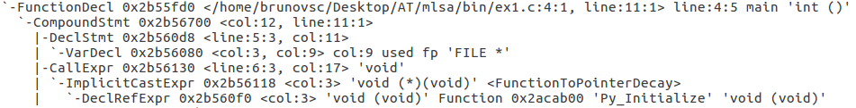 Figure 1: Portion of a C AST file
the AST module and the file ast2json.py
Figure 1: Portion of a C AST file
the AST module and the file ast2json.py Figure 2: Portion of a Python AST json file
And SpiderMonkey
Figure 2: Portion of a Python AST json file
And SpiderMonkey Figure 3: Portion of a JavaScript AST json file
The AST files have very different structures for C, Python and Javascript, but the parsers are designed to handle each kind of AST differently. Those parsers filter the AST files, detecting and recording function calls and their arguments. Initially, the program is capable of detecting literals and variables as arguments. Reaching Definition Analysis has been implemented for C/C++ programs that call Python programs (but none of the other languages) to handle statically assigned variables as arguments to functions. The current version of the program handles part of the Python.h interface between C and Python. It only analyzes PyRun_SimpleFile calls. Other mechanisms for calling Python from C will also be implemented in the future. The version can also handle PyV8 's eval function to call a JavaScript program from Python, and JQuerry's ajaz function to call a Python program from JavaScript. In the future, the program will be able to handle cases in which a JavaScript program is called from a C program, and both JavaScript and Python functions call C programs.
Figure 3: Portion of a JavaScript AST json file
The AST files have very different structures for C, Python and Javascript, but the parsers are designed to handle each kind of AST differently. Those parsers filter the AST files, detecting and recording function calls and their arguments. Initially, the program is capable of detecting literals and variables as arguments. Reaching Definition Analysis has been implemented for C/C++ programs that call Python programs (but none of the other languages) to handle statically assigned variables as arguments to functions. The current version of the program handles part of the Python.h interface between C and Python. It only analyzes PyRun_SimpleFile calls. Other mechanisms for calling Python from C will also be implemented in the future. The version can also handle PyV8 's eval function to call a JavaScript program from Python, and JQuerry's ajaz function to call a Python program from JavaScript. In the future, the program will be able to handle cases in which a JavaScript program is called from a C program, and both JavaScript and Python functions call C programs.
When the designated function used to call another program of another language, such as PyRun_SimpleFile , JSContext().eval() or $.ajax(), is found, its argument (name of the Python or JavaScript file) is considered a function call and the executable portion of that file is represented as the main function in the original program. That creates the connection between the two files, which allows the subsequent programs to build the call graph.
mergeFunCall.py combines all individual csv files from the list of source files into one. This file is then used as input to generateDot.py. This program translates the csv file to a dot file, which represents the csv file as a graph. The Dot program builds the final graph via GraphViz and saves it as a PDF file. Circular nodes represent C programs, rectangular nodes represent Python programs, and hexagonal nodes represent JavaScript programs. Recursive functions are denoted by dashed nodes. Errors, such as circularity in a system or unidentifiable interoperability, are denoted by double-lined dashed nodes.
 Figure 4: Example of a multilingual call graph
Permissions
- Persons/group who can view/change the page:
- Set ALLOWTOPICCHANGE = FRCVRoboticsGroup
 Execution
To run the software:
On the terminal, run the mlcg command with the desired folder or programs as arguments: - $mlcg.py [list of args]
- $mlcg.py test/test5
Permissions
- Persons/group who can view/change the page:
- Set ALLOWTOPICCHANGE = FRCVRoboticsGroup
 Future Work
- Extension of the RDA analysis for more complex interoperability aPIs, including use of DATALOG for analysis
- More extensive testing and comparisons of the CGs generated with those for existing CG tools
- Handling other ways of calling Python
- PyAPI _FUNC(int) PyRun _AnyFileExFlags(FILE *fp, const char *filename, int, PyCompilerFlags *);
- PyAPI _FUNC(int) PyRun _SimpleStringFlags(const char * command, PyCompilerFlags *);
- also PyRun _SimpleString
- "command" is the python command(s) to be executed. The function will create a main function to add and run what is defined in "command"
- the string can be filtered to find default Python functions
- using a default name for this kind of python call to represent it in the graph (numbered default name to differ calls)
- PyAPI _FUNC(int) PyRun _InteractiveOneFlags(FILE *fp, const char *filename, PyCompilerFlags *);
- also PyRun _InteractiveOne
- fp is an interactive device (console, terminal) and filename is the name of the file
- executes only ONE statement from "filename"
- PyAPI _FUNC(int) PyRun _InteractiveLoopFlags(FILE *fp, const char *filename, PyCompilerFlags *);
- Also PyRun _InteractiveLoop
- fp is an interactive device (console, terminal) and filename is the name of the file
- executes statements from "filename"
- PyAPI _FUNC(PyObject *) PyRun _StringFlags(const char *str, int start, PyObject *globals, PyObject *locals, PyCompilerFlags *);
- Also PyRun _String
- runs "str" in the context specified by "globals" and "locals"
- create a default function name for this kind of call, then use it as nodes in the graph
- PyAPI _FUNC(PyObject *) PyRun _FileExFlags(FILE *, const char *, int, PyObject *, PyObject *, int, PyCompilerFlags *);
- Pure Embedding (most safe and complete way of calling python)
- see for the original code: https://docs.python.org/3/extending/embedding.html
- Process:
- see for the original code: https://docs.python.org/3/extending/embedding.html
- pFunc = PyObject _GetAttrString(PyObject *pModule, const char *func);
- func is the name of the function inside the module.
- pValue = PyObject _CallObject(PyObject *pFunc, PyObject *pArgs);
- pArgs is the list of arguments. pValue is the return value of the function. It must be converted to a C type
Future work for Pybind11
- Handling of C++ defined function import rather than whole C++ module import in Python file.( E.g., from example import Pet)
- Handling situation where the function is defined in the pybind11 binding statement. (E.g., m.def("add",[](int a){ return a+a;}) )
- Handling cases of function overloading i.e., more than one function defined with the same name but different parameters.
Permissions
- Persons/group who can view/change the page:
- Set ALLOWTOPICCHANGE = FRCVRoboticsGroup
 Installation
Pre-Requirements
- Clang 3.8 On Ubuntu terminal, type the following commands to install Clang 3.8:- sudo apt-get install clang-3.8
- sudo apt-get install python
- sudo apt-get install libmozjs-24-bin
- sudo apt-get install graphviz
MLSA
Finally clone the MLSA repository, which will generate the mlsa folder:- Download software from https://git.io/MLSA
- Run mlsapath.bash in the mlsa folder (adds mlcg.py to PATH) with command: $source mlsapath.bash
- Bin - contains python code implementing MLSA filter programs and MLSA pipeline
- Doc - contains MLSA documentation
- Test - contains the program testcode.py and test folders test0 through test5 that can be used to determine a correct installation
- ExampleCodeBase - contains C/C++, Python, and JavaScript subfolders with various programs downloaded from the web to evaluate MLSA
- $python testcode.py -1 -> deletes all code generated from testcode.py; run after every test
- $python testcode.py 0 -> tests the C function call generator
- $python testcode.py 1 -> tests the C control flow, assignment collector, and RDA pipeline
- $python testcode.py 2 -> tests the Python function call generator
- $python testcode.py 3 -> tests the multilingual Python and C functional call pipeline
- $python testcode.py 4 -> tests the JavaScript function call generator
- $python testcode.py 5 -> tests the multilingual Python, C, and JavaScript pipeline
Permissions
- Persons/group who can view/change the page:
- Set ALLOWTOPICCHANGE = FRCVRoboticsGroup
 Known Issues
C
- Cannot handle any python calls other than the "PyRun_SimpleFile" call.
- Cannot handle redefinitions of functions (functions with the same name as functions in standard libraries)
- Cannot handle cases when the name of the source file contains spaces
- Definitions in external C files can only be caught with the inclusion of a header file
- Doesnt handle "dynamic dispatch" at all, and therefore cannot determine when a certain class's member function is called
- handles these cases simply with "OBJ.call()"
Python
- Doesnt handle lambda functions, although it catches them in function calls
- Doesnt handle "dynamic dispatch" at all, and therefore cannot determine when a certain class's member function is called
- handles these cases simply with "OBJ.call()"
- Cannot handle function calls inside lambda functions (links them to the outer function)
JavaScript
- Cannot handle classes
- Cannot handle function calls inside Anonymous Functions (links them to the outer function)
- Cannot handle other JavaScript program's functions being invoked, as there is no set protocol for this
- Doesnt handle "dynamic dispatch" at all, and therefore cannot determine when a certain class's member function is called
- handles these cases simply with "OBJ.call()"
Pybind11
- Some repositories requires to add link for Eigen , Pybind11 or other folders. Otherwise the C++ function calls are not found in the AST file of the source file.
- Processing speed of mlcg.py gets slowed down when running on Pybind11 repositories.
- Handling a situation where function is imported from the C++ module instead of the whole module. (E.g.,from example import Pet)
Permissions
- Persons/group who can view/change the page:
- Set ALLOWTOPICCHANGE = FRCVRoboticsGroup
 System Requirements
- Linux Ubuntu 14.04
- SpiderMonkey 24
- Clang 3.8
- Python 2.7
- GraphViz 2.38
- ps2pdf
- Evince or other PDF viewer
- Bash 4.3
- Check INSTALLATION section for instructions on installing the required features.
Permissions- Persons/group who can view/change the page:
- Set ALLOWTOPICCHANGE = FRCVRoboticsGroup
Welcome to the Fordham University Robotics & Computer Vision Laboratory
Goto the Main Lab Home Page- Persons/group who can change the list:
- Set ALLOWTOPICCHANGE = FRCVLabGroup
In the News
* 4th Machine Intelligence Day- Persons/group who can change the list:
- Set ALLOWTOPICCHANGE = FRCVLabGroup
 A group of 16 high achieving MS/HS students from the Bronx Laboratory School of Finance and Technology visited the Fordham Robotics lab January 25th 2019.
They received a series of hands-on demos from some of the students who work in the lab.
Kasper Grispino demonstrated coordinated control of the swarm of Crazyflie quadcopter drones that he is doing research with. His research focuses on human-drone interactions. He displayed various computer controlled drone swarm activities, which consisted of randomly generated flight paths that controlled the angles of flight using calculus. In addition, Kasper demoed the use of camera information to allow a drone to respond and move based on his body movements using computer vision.
Trung Nguyen demonstrated the open-source robot operating system ROS and showed how it could be used to control some Pioneer 3-At ground robots. One of ROS' features permits the Pioneer to display laser and sonar data to other computers. Additionally, he offered students the opportunity to issue commands using a python program to control a Pioneer in parking itself in a designated location.
A group of 16 high achieving MS/HS students from the Bronx Laboratory School of Finance and Technology visited the Fordham Robotics lab January 25th 2019.
They received a series of hands-on demos from some of the students who work in the lab.
Kasper Grispino demonstrated coordinated control of the swarm of Crazyflie quadcopter drones that he is doing research with. His research focuses on human-drone interactions. He displayed various computer controlled drone swarm activities, which consisted of randomly generated flight paths that controlled the angles of flight using calculus. In addition, Kasper demoed the use of camera information to allow a drone to respond and move based on his body movements using computer vision.
Trung Nguyen demonstrated the open-source robot operating system ROS and showed how it could be used to control some Pioneer 3-At ground robots. One of ROS' features permits the Pioneer to display laser and sonar data to other computers. Additionally, he offered students the opportunity to issue commands using a python program to control a Pioneer in parking itself in a designated location.


Permissions
Persons/group who can view/change the page:- Set ALLOWTOPICCHANGE = FRCVRoboticsGroup
Faculty & Collaborators
Dr. Damian M. Lyons, Lab Director. Professor of Computer and Information Science. Dr. Mohamed Rahouti, CIS Department/Fordham Dr. D. Leeds, CIS Department/Fordham Dr. Paul Benjamin, PACE University Dr. Tom Marshall, Bloomberg NYC Mr. Avi Shuter, Senior Wild Animal Keeper, Bronx Wildlife Conservancy, Bronx Zoo Dr. Ronald Arkin, Georgia Institute of Technology Dr. J. MacDonall, Professor of Psychology/Fordham Dr. D. Frank Hsu, Clavius Distinguished Professor/FordhamGraduate Students
Nasim PaykariFRCV Lab Assistant(s)
Jary TolentinoUndergraduate Students
**Summer Researchers
**Graduate Alums
Dylon Rajah Kyle Ryan Dino Becaj Qian Zhao Saba Zara Anne Marie Bogar Trevor Buteau Caleb Hulbert Felix Fang Feng Tang Peng Tang Dagan Harrington Paramesh Nirmal Tsung-Ming (James) Liu Karma Shrestha Stephen Fox Giselle Isner Kiran Pamnany Jeremy Drysdale Sothearith Chanty Liang Wong Qiang Ma Jizhou Ai Linta Samuel Ben Weigend Carlos Usandivaras Hemamalini Kannan Franklin MonteroUndergraduate Alums
Noah Petzinger Jason Hughes Philip Bal Kasper Grispino Mark Huang Michael Wieck-Sosa Doug Lamport Trung Nguyen Sunand Ragupathi Nicholas Estelami Juan Ruiz Ben Barriage Luca Del Signore Maggie Gates Aryadne Guardieiro Pereira Rezende (BSMP 2016) Margaret Adams Alex Keyes Nicholas Primiano Dennis Egan Joseph Leroy Alina Kinealy Emir Ogel Kenneth Durkin Kelly Cunningham Chris Guerrero Andrew Fraser Michael Yu Liz Spangler Brendan Offer Pamela Pettit Sasha-Lee Garvey Alex Dorey Mike Feola Yu Lam Brittany Kwait Peter To Paul Ryan Rene McQuick Michelle Yee Erland Jean-Pierre Mike Welsh Kate McCarthy Jesus RodriguezHonorary Alums!
Rohan Agarwal (Hunter College High School; Summer 2018) Bruno Vieira (BSMP 2016) Gleidson Mendes (BSMP 2015) Nicholas Estelami (Summer 2013) Alicia Devalencia (Stuyvesant HS; Summer 2012) Oliver Donson (Ossining HS) Greg Robins (Ossining HS) Dan Scanteianu (Ossining HS)- Persons/group who can change the list:
- Set ALLOWTOPICCHANGE = FRCVLabGroup
Overview of Research Projectsin Progress at the FRCV Lab
Wide Area Visual Navigation (WAVN)
We are investigating a novel approach to navigation for a heterogenous robot team operating for long durations in an environment where there is long and short term visual changes. Small-scale precision agriculture is one of our main applications: High precision, high reliability GPS can be an entrance barrier for small family farms. A successful solution to this challenge would open the way to revolutionizing small farming to compete with big agribusiness. The challenge is enormous however. A family farm operating in a remote location, experiencing all the changes in terrain appearance and navigability that comes with seasonal weather changes and dramatic weather events. Our work is a step in this direction. Our approach is based on visual homing, which is a simple and lightweight method for a robot to navigate to a visually definied target that is in its current field of view. We extend this approach to work with targets that are beyond the current field of view by leveraging visual information from all camera assets in the entire team (and potentially fixed camera assets on buildings or other available camera assets). To ensure efficient and secure distributed communication between the team, we employ distributed blockchain communication: Team members regularly upload their visual panorama to the blockchain, which is then available to all team members in a safe and secure fashion. When a robot needs to navigate to a distant target, it queries the visual information from the rest of the team, and establishes a set of intermediate visual targets it can sequentially navigate to using homing, ending with the final target.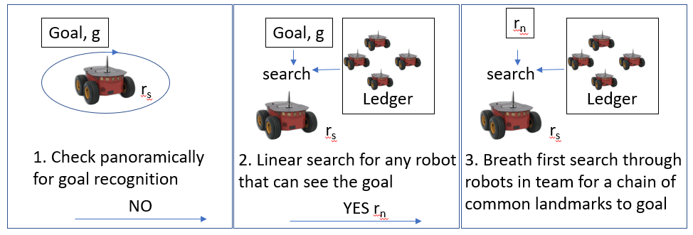 For a short video introduction, see here.
We are also investigating the synergy of blockchain and navigation methodologies to show that blockhain can be used to simplify navigation in addition to providing a distributed and secure communication channel.
Key to the WAVN navigation approach is establishing an intermediate sequence of landmarks by looking for a chain of common landmarks between pairs of robots. We have investigated different ways in which robots can identify whether they are seeing the same landmark and we show that using a CNN-bsed YOLO to segement a scene into common objects followed by feature matching to identify whether objects are the same outperforms featrure matching on its own. Furthermore using a group of objects as a landmark outperforms a single object landmark. We are currently investigating whether object diversity in a group improves this even further.
For a short video introduction, see here.
We are also investigating the synergy of blockchain and navigation methodologies to show that blockhain can be used to simplify navigation in addition to providing a distributed and secure communication channel.
Key to the WAVN navigation approach is establishing an intermediate sequence of landmarks by looking for a chain of common landmarks between pairs of robots. We have investigated different ways in which robots can identify whether they are seeing the same landmark and we show that using a CNN-bsed YOLO to segement a scene into common objects followed by feature matching to identify whether objects are the same outperforms featrure matching on its own. Furthermore using a group of objects as a landmark outperforms a single object landmark. We are currently investigating whether object diversity in a group improves this even further.
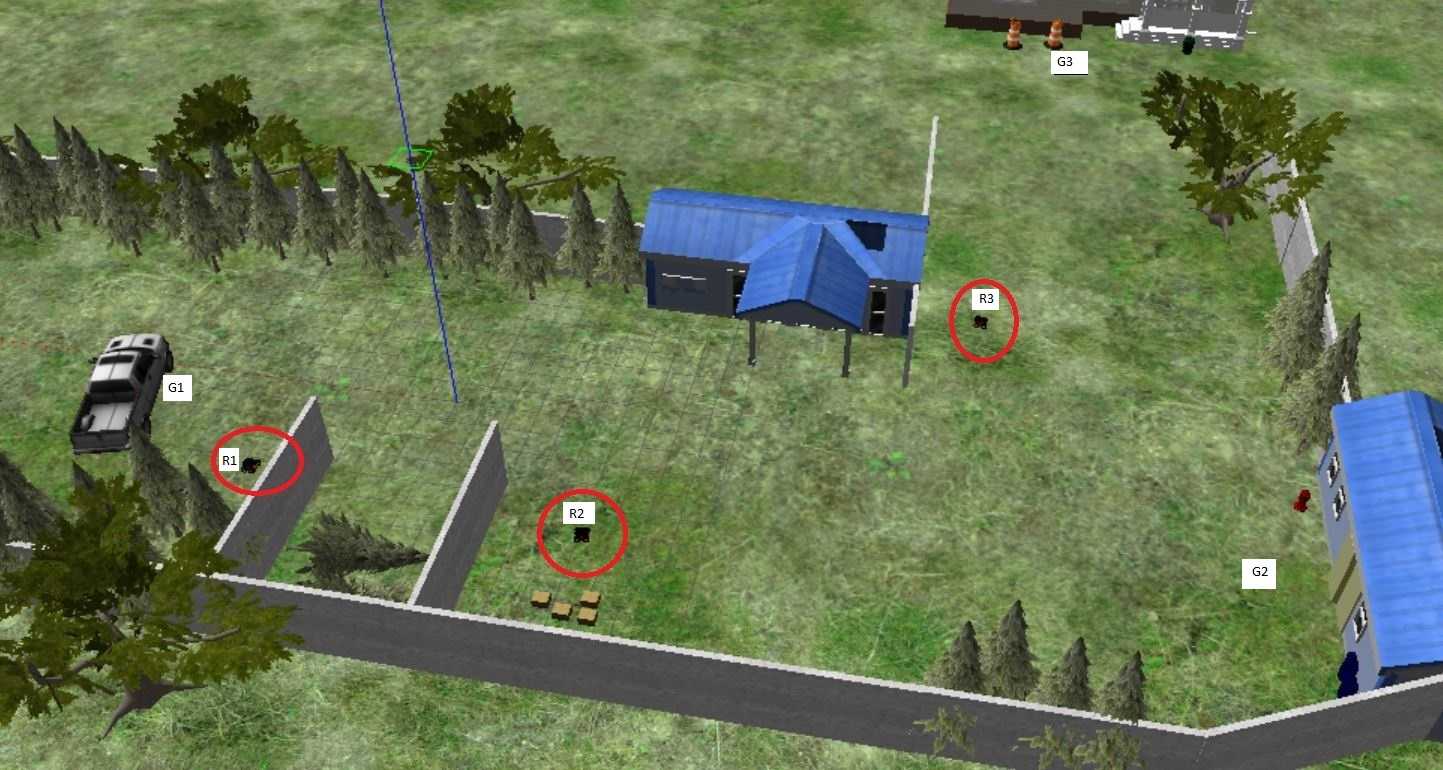 We have conducted WAVN experiments using grid-simulations, ROS/Gazebo simulations and lab experiments.using Turtlebot3 and Pioneer robots. The image above shows a Gazebo simulation of 3 pioneer robots in a small outdoor work area with plenty of out of view targets to navigate to. Our next step is to use WAVN for outdoor navigation to campus locations using a team of Pioneer robots.
Using Air Disturbance Detection for Obstacle Avoidance in Drones
The use of unmanned aerial vehicles (drones) is expanding to commercial, scientific, and agriculture applications, such as surveillance, product deliveries and aerial photography etc. One challenge for applications of drones is detecting obstacles and avoiding collisions. Especially small drones in proximity to people need to detect people around them and avoid injuring those people. A typical solution to this issue is the use of camera sensor, ultrasonic sensor for obstacle detection or sometimes just manual control (teleoperation). However, these solutions have costs in battery lifetime, payload, operator skill. Due to their diminished ability to support any payload, it is difficult to put extra stuff on small drones. Fortunately, most drones are equipped with an inertial measurement unit (IMU). The IMU can tell us the drones attitude and accelerations from the gyroscope and accelerometer. We note that there will be air disturbance in the vicinity of the drone when its moving close to obstacles or other drones. The data from the gyroscope and accelerometer will change to reflect this. Our objective is to detect obstacles from the aforementioned air disturbance by analyzing the data from the gyroscope and accelerometer. Air disturbance can be produced by many reasons such as ground effect, drones in proximity to people or wind gust from other sides. These situations can occur at the same time to make things more complicated. To make the experiment simpler, we just detect air disturbance produced from flying close to or underneath an overhead drone. We choose a small drone, the Crazyflie 2.0, as the experiment tool. The Crazyflie 2.0 is a lightweight, open source flying development platform based on a micro quadcopter. It has several built-in sensors including gyroscope, accelerometer etc. ROS (Robot Operating System) is a set of software libraries and tools for modular robot applications. The point of ROS is to create a robotics standard. ROS has great simulation tools such as Rviz and Gazebo to help us to run the simulation before conducting real experiments on drones. Currently there is little Crazyflie support in ROS, 4 however, we wish to use ROS to conduct our experimentation because it has become a de facto standard. More details hereMultilingual Software Analysis (MLSA)
Multilingual Software Analysis (MLSA) or Melissa is a lightweight tool set developed for the analysis of large software systems which are multilingual in nature (written in more than one programming language). Large software systems are often written in more than one programming language, for example, some parts in C++, some in Python etc. Typically, software engineering tools work on monolingual programs, programs written in single language, but since in practice many software systems or code bases are written in more than on language, this can be less ideal.
Melissa produces tools to analyze programs written in more than one language and generate for example, dependency graphs and call graphs across multiple languages, overcoming the limitation of software tools only work on monolingual software system or programs.
Leveraging the static analysis work developed for DTRA, we are looking at multilingual to provide refactoring and other information for very large, multi language software code bases. This project is funded by a two year grant from Bloomberg NYC. The objective of the project is to make a number of open-source MLSA tools available for general use and comment. For more details, see here.

TOAD Tracking: Automating Behavioral Research of the Kihansi Spray Toad
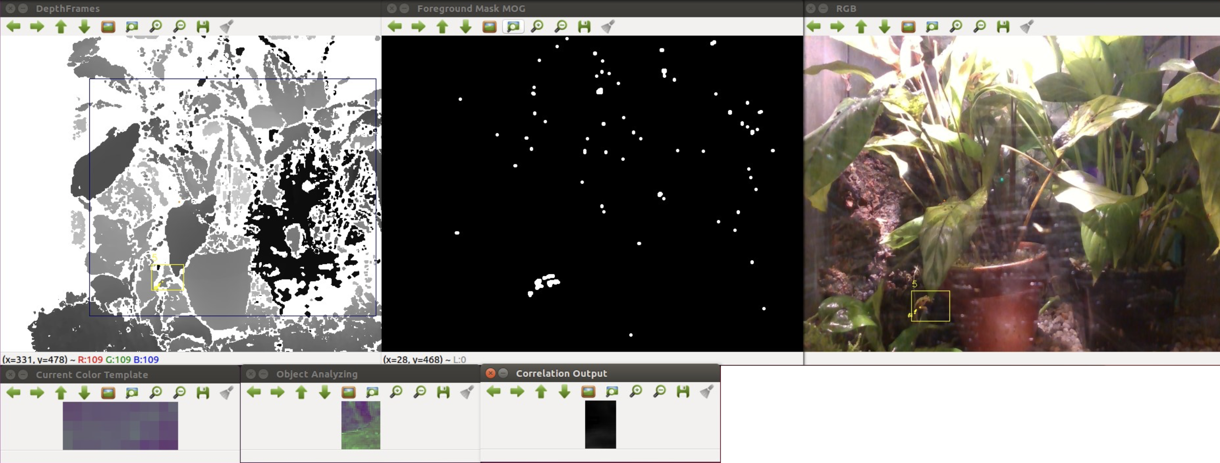
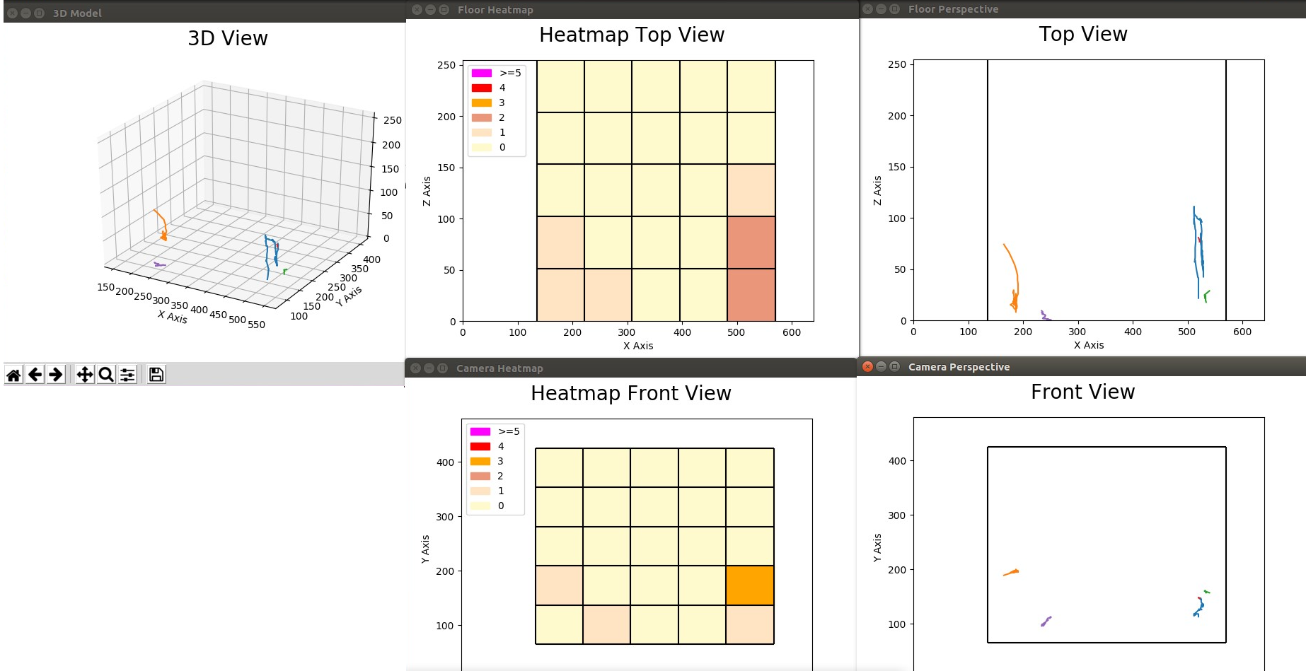
Getting it right the first time! Establishing performance guarantees for C-WMD autonomous robot missions
In research being conducted for the Defense Threat Reduction Agency (DTRA), we are concerned with robot missions that may only have a single opportunity for successful completion, with serious consequences if the mission is not completed properly. In particular we are investigating missions for Counter-Weapons of Mass Destruction (C-WMD) operations, which require discovery of a WMD within a structure and then either neutralizing it or reporting its location and existence to the command authority. Typical scenarios consist of situations where the environment may be poorly characterized in advance in terms of spatial layout, and have time-critical performance requirements. It is our goal to provide reliable performance guarantees for whether or not the mission as specified may be successfully completed under these circumstances, and towards that end we have developed a set of specialized software tools to provide guidance to an operator/commander prior to deployment of a robot tasked with such a mission. We have developed a novel static analysis approach to analysing behavior based programs, coupled with a Bayesian network approach to predicting performance. Comparing predicted results to extensive empirical validation conducted at GATech's mobile robots lab, we have shown we can verify/predict reasltic performance for waypoint missions, multiple robot missions, missions with uncertain obstacles, missions including localization software. We are currently working on human-in-the-loop systems.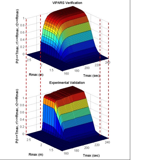
Space-Based Potential Fields: Exploring buildings using a distributed robot team navigation algorithm
. In this work we propose an approach, the Space-Based Potential Field (SBPF) approach, to controlling multiple robots for area exploration missions that focus on robot dispersion. The SBPF method is based on a potential field approach that leverages knowledge of the overall bounds of the area to be explored. This additional information allows a simpler potential field control strategy for all robots but which nonetheless has good dispersion and overlap performance in all the multi-robot scenarios while avoiding potential minima. Both simulation and robot experimental results are presented as evidence.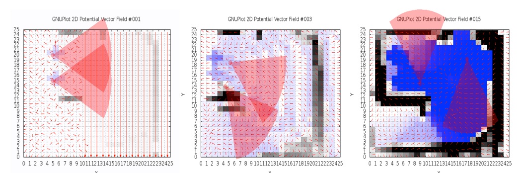
Visual Homing with Stereovision
Visual Homing is a navigation method based on comparing a stored image of a goal location to the current image to determine how to navigate to the goal location. It is theorized that insects such as ants and bees employ visual homing techniques to return to their nest or hive. Visual Homing has been applied to robot platforms using two main approaches: holistic and feature-based. Both methods aim at determining the distance and direction to the goal location. Visual navigational algorithms using Scale Invariant Feature Transform (SIFT) techniques have gained great popularity in the recent years due to the robustness of the SIFT feature operator. There are existing visual homing methods that use the scale change information from SIFT such as Homing in Scale Space (HiSS). HiSS uses the scale change information from SIFT to estimate the distance between the robot and the goal location to improve homing accuracy. Since the scale component of SIFT is discrete with only a small number of elements, the result is a rough measurement of distance with limited accuracy. We have developed a visual homing algorithm that uses stereo data, resulting in better homing performance. This algorithm, known as Homing with Stereovision utilizes a stereo camera mounted on a pan-tilt unit, which is used to build composite wide-field images. We use the wide-field images coupled with the stereo data obtained from the stereo camera to extend the SIFT keypoint vector to include a new parameter depth (z). Using this information, Homing with Stereovision determines the distance and orientation from the robot to the goal location. The algorithm is novel in its use of a stereo camera to perform visual homing. We compare our method with HiSS in a set of 200 indoor trials using two Pioneer 3-AT robots. We evaluate the performance of both methods using a set of performance metrics described in this paper and we show that Homing with Stereovision improves on HiSS for all the performance metrics for these trials. In current work we have modified the HSV code to use a database of stored stereoimagery and we are conducting extensive testing of the algorithm.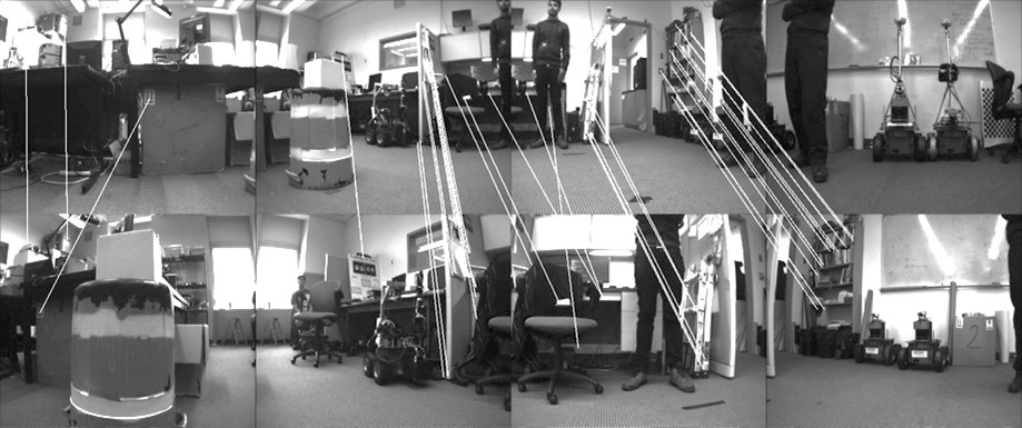
Ghosthunters! Filtering mutual sensor interference in closely working robot teams
We address the problem of fusing laser ranging data from multiple mobile robots that are surveying an area as part of a robot search and rescue or area surveillance mission. We are specifically interested in the case where members of the robot team are working in close proximity to each other. The advantage of this teamwork is that it greatly speeds up the surveying process; the area can be quickly covered even when the robots use a random motion exploration approach. However, the disadvantage of the close proximity is that it is possible, and even likely, that the laser ranging data from one robot include many depth readings caused by another robot. We refer to this as mutual interference. Using a team of two Pioneer 3-AT robots with tilted SICK LMS-200 laser sensors, we evaluate several techniques for fusing the laser ranging information so as to eliminate the mutual interference. There is an extensive literature on the mapping and localization aspect of this problem. Recent work on mapping has begun to address dynamic or transient objects. Our problem differs from the dynamic map problem in that we look at one kind of transient map feature, other robots, and we know that we wish to completely eliminate the feature. We present and evaluate three different approaches to the map fusion problem: a robot-centric approach, based on estimating team member locations; a map-centric approach, based on inspecting local regions of the map, and a combination of both approaches. We show results for these approaches for several experiments for a two robot team operating in a confined indoor environment .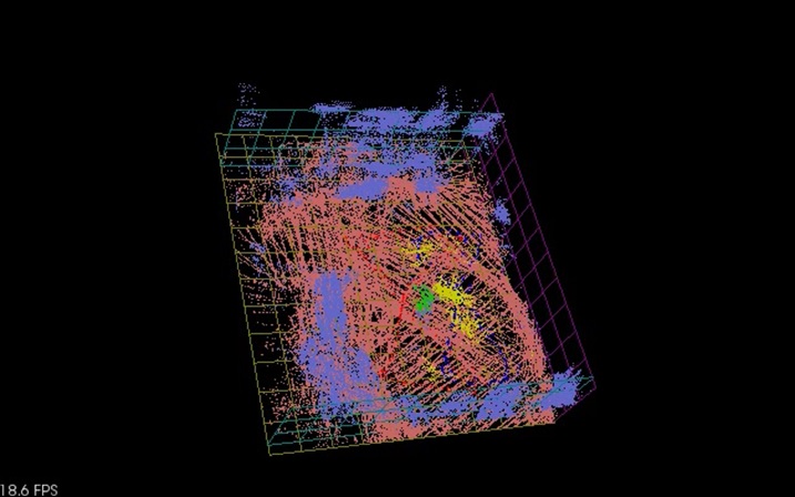
Drone project : Crazyflie
Drones are an exciting kind of robot that has recently found their way into commercial mainstream robotics. The most recent high-profile example of this is their appearance in the opening ceremonies of the 2018 Winter Olympics in Pyeong Chang, South Korea. Due to their epic appearance, the drones received high acclaim from the audience, solidifying the idea of using drones as performers in a public arena, capable of carrying out emotion-filled acts. Beyond this example, our vision is to utilize drones, more specifically drone swarms, to not only perform theatrical performances, but also operate as a collective entity that can communicate and interact meaningfully with ordinary people in daily life activities. Our thesis is that drone swarms can more effectively impart emotive communication than solo drones. For instance, drone swarms can play the role of a tour guide at attractions or museums, to bring tourists on a trip through the most notable points at the site. In emergency situations that require evacuation of large crowds, drone swarms can help guide and coordinate the movement of survivors towards safe areas, as well as signaling first responders towards areas where help is needed the most.Advantages of Drone Swarms
The main advantages of drone swarms over solo drones are the added dimensions of freedom. More specifically, with multiple drones, we can- Harness the 3D space in the form of occupancy volume. Drones can be commanded to spread apart or come close to one another, as well as hover in space at specific relative positions to one another, to depict different shapes of varying volume.
- Express group-based dynamic properties such as coordination or synchronization, similar to team dance with human dancers.
- Depict emotional states with collective group-based motions. Specifically, the movement velocity of individual drones in a swarm, either relative to each other or as absolute values, can be tweaked to depict internal states of emotions. For instance, while keeping the collective velocity zero, agitation can be expressed by fast moving drones, while calmness can be depicted by constant and slow motions, causing a therapeutic effect.
- Convey metaphorical messages in the form of sketches that involve more than one entities. For instance, depicting the notions of reciprocal love or fighting is much easier done using two or more drones than with single ones.
Motivating Applications
Equipped with the ability to impart emotive messages, drone swarms could be used for crowd control and guidance, e.g.,- Shepherding groups of visitors around a site such as tourists visiting a location, or school groups visiting a museum or zoo. In this scenario, the drone swarm form boundaries around the group and shepherd them around. In addition, the swarm can behave in a manner to elicit emotions, such as excitement, as particular stations on the tour or landmarks are encountered.
- Controlling crowds in a large gathering such as a music concert or a large community meeting. In this scenario, the drone swarm needs to keep the crowd within the confines of the meeting and patrol the crowd boundaries to prevent
access to prohibited areas. Emergencies happening in such large crowds, e.g., a person feeling ill or a fight breaking out, can pose challenges. - Advertising produces and stores to passing crowds of potential customers. In this scenario, the swarm can be deployed at the entrance of shops or attractions, attracting customers to products or stores in a non-invasive way. For example, they can spell out the names or the shapes of the products being sold. Since the drones are airborne and do not occupy any ground space, they will not interfere with uninterested passers-by.
Technical Challenges
In order to construct drone swarms that can communicate, interact with, and operate within the public space, we believe that the following technical challenges need to be addressed. This project page is hereOlder Projects
This includes the following projects that are temporarily on hiatus: - Spatial Stereograms: a 3D landmark representation - Efficient legged locomotion: Rotating Tripedal Mechanism - Cognitive Robotics: ADAPT. Synchronizing real and synthetic imagery.- Persons/group who can view/change the page:
- Set ALLOWTOPICCHANGE = FRCVRoboticsGroup
Fordham Robotics and Computer Vision Lab Publications
All recent publications now hosted at Fordham University Digital Commons and can be downloaded from there.
To got to the Digital Commons publications list CLICK HEREDamian M. Lyons, Saba B. Zahra, and Thomas M. Marshall, Towards Lakosian Multilingual Software Design Principles 14th Int. Conf. on Software Technologies (ICSoft) Porto Portugal, July 2019. https://fordham.bepress.com/frcv_facultypubs/63/
Pre 2003
Brodsky, T.; Cohen, R.; Cohen-Solal, E.; Gutta, S.; Lyons, D.; Philomin, V.; Trajkovic, M. Visual surveillance in retail stores and in the home. Invited paper. 2nd European Workshop on Advanced Video Based Surveillance Systems, 9/4/2001, Kingston upon Thames, London, UK Gutchess, D., Trajkovic, Cohen-Solal, E., M., Lyons, D., Jain, A., A Background Model Initialization Algorithm for Video Surveillance, Int. Conf. on Comp. Vision 2001. Lee, M-S., Weinshall, D., Colmenarez, A., Cohen-Solal, E., Lyons, D., Identifying a 3-D pointing target with 2-D homography and line intersection Int. Conf. on Comp. Vision 2001. Lyons, D.M. et al., Automated CCTV Surveillance using Computer Vision Technology, Philips Digital Video Technologies Workshop 2000, Briarcliff NY. Lyons, D.M. & Pelletier, D., A Line-Scan Computer Vision Algorithm for Identifying Human Body Features in: GW99 (Eds. A. Braffart et al.) Lecture Notes in AI #1739, Springer Verlag 2000. Lyons, D.M.,A Schema-Theory Approach to Specifying and Analysing the Behavior of Robotic Systems in: Prerational Intelligence, (Eds. Ritter, Cruse & Dean) Kluwer Academic, Dordrecht/Boston/London 2000. Lyons, D.M. et al.,Video Content Analysis for Surveillance, Philips DSP Conference 1999, Eindhoven NL. Lyons, D.M., A Field of View based Camera Control Interface. Philips Newsletter #185 1999. Lyons, D.M., Pelletier, D.L., and Knapp, D.C., Multimodal Interactive Advertising. Workshop on Perceptual User Interfaces (PUI98) November 5-6, 1998, San Francisco, CA. Murphy, T., and Lyons, D. Combing Direct and Model-Based Perceptual Information Through Schema Theory, 1997 IEEE International Symposium on Computational Intelligence in Robotics and Automation (CIRA97) , July 1997, Monterey, CA. Lyons, D.M. and Murphy, T.G., Gesture Interpretation from Video Input. Philips Research Bulletin on Systems and Software 21, July 1997. Lee, S., Lyons, D., Ramos, C., Troccaz, J. Guest Editorial: Special Issue on Assembly and Task Planning. IEEE Trans. Rob. & Aut. V.12 N.2 April 1996. Lyons, D.M. and Hendriks, A., Planning as Incremental Adaptation of a Reactive System. Journal of Robotics & Autonomous Systems 14, 1995, pp.255-288. Lyons, D.M. and Hendriks, A., Exploiting Patterns of Interaction to Achieve Reactive Behavior. Special Issue on Computational Theories of Interaction, Artificial Intelligence 73, 1995, pp.117-148. Lyons, D.M., Book Review of David Chapman's Vision, Instruction, and Action Special Issue on Computational Theories of Interaction, Artificial Intelligence, Eds. P. Agre & S. Rosenschein, 73, 1995. Lyons, D.M., Representing and Analyzing Action Plans as Networks of Concurrent Processes. IEEE Transactions on Robotics and Automation June 1993. Lyons, D.M. and Hendriks, A., ADAPT: A Toolkit for Fast Prototyping of Embedded Software. Philips Research Bulletin on Software & Systems July 1993. Hendriks, A. and Lyons, D.M., A Methodology for Creating and Adapting Reactive Systems. IEEE Journal on Tools for AI 1993. Lyons, D.M., A Camera-Based User Interface. Philips Newsletter #167 1996. Gottschlich, S., Ramos, C., Lyons, D., Assembly and Task Planning: A Taxonomy. IEEE Robotics & Automation Magazine V1 N3 Sept. 1994. Lyons, D.M., and Hendriks, A., A Toolkit for Designing and Evaluating Discrete-Event Control Strategies. Philips Research Newsletter April 1992. Lyons, D., Murphy, T., and Hendriks, A., Deliberation and Reaction as Decoupled, Concurrent Activities. ICRA'96 Workshop on Robotic Planning & Execution (invited) April 1996, Minneapolis, MN. Lyons, D.M. and Hendriks, A., Testing Adaptive Planning, 2nd International Conference on AI Planning Systems, June 1994, ChicagoIL. Lyons, D.M. and Hendriks, A.J., Adaptive Planning: An Approach that Views Errors as Assumption Failures, AAAI Spring Symposium on Detecting and Resolving Errors in Manufacturing Systems March 1994. Lyons, D.M. and Hendriks, A., Planning by Adaptation: Experimental Results, IEEE Int. Conf. on Rob. & Aut., San DiegoCA, May 1994. Lyons, D.M. and Hendriks, A., Safely Adapting a Hierarchical Reactive System. SPIE Intelligent Robots and Computer Vision XII September 1993. Murphy, T., Lyons, D.M. and Hendriks, A., Stable Grasping with a Multi-Fingered Robot Hand: A Behavior-Based Approach, Intelligent Robots and Systems (IROS) Japan 1993. Lyons, D.M. and Hendriks, A., A Practical Approach to Integrating Reaction and Deliberation. First AI Conference on Planning Systems, Univ. of Maryland, College ParkMD, 1992. Lyons, D.M. and Hendriks, A., Planning for Reactive Robot Behavior. IEEE Int. Conf. on Robotics and Automation Nice, France 1992. Lyons, D.M. and Hendriks, A.J., Achieving Robustness by Casting Planning as Adaptation of a Reactive System. IEEE Int. Conf. on Robotics and Automation, SacramentoCA, April 1991. Lyons, D.M. and Hendriks, A. Planning and Acting in Real-Time 13th IMACS World Congress on Comp. and Applied Math. TrinityCollege, Dublin, July 1991. Lyons, D.M. and Hendriks, A., Implementing an Integrated Approach to Planning and Reaction. SPIE Conf. on Intelligent Robots and Computer Vision: Algorithms and Techniques. BostonMA, November 1991. Lyons, D.M. and Allton, J.H., Achieving a Balance between Teleoperation and Autonomy in Specifying Plans for a Planetary Rover, SPIE Symposium on Advances in Intelligent Systems; Cooperative Intelligent Robotics in Space, Boston, MA, Nov. 1990. Gopinath, P., Lyons, D.M. and Mehta, S., Representation and Execution Support for Reliable Robot Applications. 9th Symp. on Reliable Distributed Systems, Huntsville, Alabama, Oct. 1990. Lyons, D.M., Mehta, S. and Gopinath, P., Robust Representation and Execution of Robot Plans, EuroMicro Real-Time Systems Workshop, Horsholm, Denmark, May 28-30th, 1990. Lyons, D.M., RS: A Formal Model for Reactive Robot Plans, 2nd RPI Int. Conf. on Computer Integrated Manufacturing Troy, NY, May 21--23, 1990. Lyons, D.M., Pelavin, R., Hendriks, A., Benjamin, P. Task Planning using a Formal Model for Reactive Robot Plans. AAAI Spring Symposium on Planning in Uncertain and Dynamic Environments. Stanford CA, Mar. 27-29th, 1990. Lyons, D.M., A Process-Based Approach to Task-Plan Representation._IEEE International Conference on Robotics and Automation_, Cincinnati, Ohio, May 1990. Hendriks, A., Lyons, D. Using Perceptions to Plan Incremental Adaptation, in: Intelligent Robots and Systems (ed. V. Graefe). 1995. Lyons, D.M., Building and Analyzing the Behavior of Autonomous Robot Systems. Center for Interdisciplinary Research (ZiF) Conf. on Prerational Intelligence, Univ. of Bielefeld, Germany, November 1993. Lyons, D.M. and Hendriks, A., Reactive Planning. Encyclopedia of Artificial Intelligence, 2nd Edition, Wiley & Sons, December, 1991. Venkataraman, S. and Lyons D.M., A Task-Oriented Architecture for Dexterous Manipulation in: Dexterous Robot Hands (Iberall T., Venkataraman, S.T., Eds.) Springer-Verlag 1990. Arbib, M.A., Iberall, T. and Lyons, D.M., Schemas that Integrate Vision and Touch for Hand Control, in: Vision, Brain and Cooperative Computation (Arbib, M.A., Hanson, A.R., Eds.), MIT Press, 1987. Iberall, T., Lyons, D.M. Perceptual Robotics: Towards a Language for the Integration of Sensation and Perception in a Dexterous Robot Handin: Management and Information Systems, Volume IILanguages for Automation (S.K. Chang, Ed.), Plenum Publishing Company, 1985. Lyons, D.M. and Mehta, S., A Distributed Computing Environment for the Multiple Robot Domain, Fourth International Conference on CAD, CAM, Robotics and Factories of the Future, New Delhi, India, Dec. 19--22nd, 1989. Lyons, D.M., Vijaykumar, R. and Venkataraman, S., A Representation for Error Detection and Recovery in Robot Task Plans. SPIE Symposium on Advances in Intelligent Robotic Systems; Intelligent Robots and Computer Vision Philadelphia PA, Nov. 7-8th, 1989. Lyons, D.M., On-Line Allocation of Robot Resources to Task Plans. SPIE Symposium on Advances in Intelligent Robotics; Expert Robots for Industrial Use, Nov. 1988. Lyons, D.M., A Novel Approach to High-Level Robot Programming. IEEE Workshop on Languages for Automation, Vienna, Austria, 1987. Lyons, D.M., Tagged Potential Fields: An Approach to the Specification of Complex Manipulator Configurations. IEEE International Conference on Robotics and Automation,San FranciscoCA, Apr. 7-11th, 1986. Lyons, D.M. and Arbib, M.A., A Task-Level Model of Distributed Computation for the Sensory-Based Control of Complex Manipulators. IFAC Symposium on Robot Control, Barcelona, Spain, Nov. 6-8th, 1985. K. Ramamritham, D. Lyons, G. Pocock and M.A. Arbib, Towards Distributed Robot Control, IFAC Symposium on Robot Control, Barcelona, Spain, Nov 1985, pp. 107-112. Lyons, D.M., A Simple Set of Grasps for a Dexterous Hand, IEEE International Conference on Robotics and Automation, St. Louis, Missouri, Mar. 25-28th, 1985. Lyons, D.M. and Arbib, M.A., A Formal Model of Computation for Sensory-based Robotics. IEEE Transactions on Robotics and Automation 5(3), Jun. 1989. Arbib, M.A., Iberall, T. and Lyons, D.M., Coordinated Control Programs for Movements of the Hand. Experimental Brain Research #10, Springer-Verlag, 1985.Technical Reports.
(1) Brodsky, T., Cohen, R., Gutta, G., Lyons, D., Retail Applications of the Video Content Analysis Module. Philips TN-2000-021 2000. (2) Lyons, D., Trajkovic, M., Briarcliff Intruder Tracking Engine V2.41 User Manual, Philips TSR-2000-011 2000. (3) Lyons, D., Brodsky, T., Cohen R., and Gutta, S., Retail Video Content Analysis Requirements Document, Philips TSR-2000-012, 2000. (4) Lyons, D., Brodsky, T., Cohen-Solal, E., and Gutta, S., Residential Video Content Analysis Requirements Document, Philips TSR-2000-010, 2000. (5) Lyons, D.M., Calculation of Floor Plan Field of View regions for Pan-Tilt-Zoom Cameras. Philips TN-99-028 1999. (6) Lyons, D.M., Knapp, D.C., and Pelletier, D.L. Vidiwall Applications of Video-Based Gesture Interpretation, Philips Research Tech. Note TN-98-003 1998. (7) Lyons, D.M., Murphy, T.F., and Pelletier, D.L. Interpretation of Arm Pointing, Philips Research Tech. Note TN-97-041 1997. (8) Lyons, D.M., Murphy, T.G. Gesture Pipes: An Efficient Architecture for Vision-Based Gesture Interpretation, Philips Research Tech. Note TN-97-039 1997. (9) Lyons, D.M. A Computer Vision System for Extracting Feature Information from Video Camera Images of People, Philips Research Tech. Report TR-97-008 1997. (10)Lyons, D.M. A Camera-Based User Interface for Multimedia and Virtual Reality Applications, Philips Research Tech. Note TN-96-031 1996. (11)Lyons, D.M. The Control of Graphical Images using Full Body Motions, Philips Research Tech. Note TN-96-028 1996. (12)Lyons, D.M., Murphy, T.G. Infowall with Camera-Based Interface, Philips Research Tech. Note TN-96-032 1996. (13)Lyons, D.M. Navigation through Virtual Reality using Camera-Based Gesture Input, Philips Research Tech. Note TN-96-030 1996. (14)Lyons, D.M. A 3-D Football Videogame using Camera-Based Gesture Input, Philips Research Tech. Note TN-96-029 1996. (15)Lyons, D.M., and Ramadorai, R.A. A White Paper on Computer-Assisted Surgery and Surgical Robotics. Philips Research Tech. Report TR-94-016 October 1994. (16)Lyons, D.M., Hendriks, A.J., Satyanarayana, S. Representation & Control of Intelligent Lighting for Commercial Buildings. Philips Research Tech. Report TR-94-029 September 1994. (17)Lyons, D.M. and Kallis, A.D. Comparisons between Lyons RS and McDermott s RPL. Philips Research Tech. Note TN-93-051 August 1993. (18)Lyons, D.M., Hendriks, A.J., Shrivastava, S., Kallis, A.D. ADAPT Simulation of Two FCMs with Buffer. Philips Research Tech. Note TN-93-050 August 1993. (19)Lyons, D.M., Hendriks, A.J., Shrivastava, S., Kallis, A.D. The ADAPT User Manual. Philips Research Tech. Report TR-93-013 May 1993. (20)Lyons, D.M., Hendriks, A. J. and Mehta, S. A Study of Adaptive Approaches to Control of the MCM-VIII. Philips Research Tech. Report TR-90-026 Sept. 1990. (21)Lyons, D.M. and Hendriks, A.J., Where is Robot Task Planning Going? Philips Research Tech. Note TN-89-149, Nov. 1989. (22)Lyons, D.M. and Mandhyan, I., Fundamentals of RS -- Part II: Process Composition. Philips Research Tech. Report TR-89-033, June 1989. (23)Lyons, D.M. Fundamentals of RS-- Part I: The Basic Model. Philips Research Tech. Report TR-89-031, June 1989. (24)Lyons, D.M. and Pelavin, R.N., An Analysis of Robot Task Plans using a Logic with Temporal Intervals. Philips Research Tech. Note TN-88-160, October 1988. (25)Lyons, D.M., A Novel Approach to High-Level Robot Programming. (Updated) Philips Research Tech. Note TN-87-039, April 1987. (26)Guida, F.C., Harosia, T.J. and Lyons, D.M., The Eindhoven Multi-Functional Gripper. Philips Research Tech. Note TN-87-145, November 1987. (27)Lyons, D.M., The Task Criterion in Grasping Philips Research Tech. Note TN-87-163, December 1987. (28)Lyons, D.M., Implementing a Distributed Control Environment for Task-Oriented Robot Control Philips Research Tech. Note TN-87-054, April 1987. (29)Lyons, D.M., Developing a Formal Model of Distributed Computation for Sensory-Based Robot Control. Philips Tech. Note TN-87-002, February 1987. (30)Lyons, D.M., A Generalization of: A Simple Set of Grasps for a Dexterous Hand. COINS Technical Report 85-37, Department of Computer and Information Science, University of Massachusetts, AmherstMA, November 1985.Patents Issued (Inventor/Co-Inventor).
(1) Computer Software to Optimize Building Lighting Energy Consumption; US pat # 5,812,422. European pat . #EP791280, 1998. (2) System and Method for Navigation through Virtual Reality using Camera-based Gesture Inputs; US pat # 6,195,104. European pat. #EP976106, 2001. (3) Motion-Based Command Generation Technology; US pat # 6,176,782, 2001. (4) A Vacuum Cleaner with Obstacle Avoidance; US pat #6,226,830, 2001. (5) Method and System for Gesture based Option Selection; US pat # 6,283,860, 2001. (6) System and Method for Constructing 3D Images using Camera-based Gesture Inputs; US pat #6,181,343, 2001. (7) Method and Apparatus to Select the Best Video Frame to Transmit for Security Monitoring; US pat # 6,411,209. European pat. #EP1346577, 2002. (8) Automated Camera Handoff for Figure Tracking in a Multiple Camera Environment; US pat # 6,359,647, 2002. (9) Method and Apparatus to Distinguish Deposit and Removal in Surveillance Video; filed 2001; US pat # 6,731,805, 2004. (10)Method for Selecting a Target in an Automated Video Tracking System; filed 2001; US pat #6,771,306, 2004. (11)Apparatus and Methods for Resolution of Exit/Entry Conflicts for Security Monitoring Systems; filed 2001; US pat. # 6,744,462. European pat. #EP1346327, 2004. (12)Method and Apparatus to Reduce False Alarms in Exit/Entrance Situations for Residential Security Monitoring; filed 2000; US pat. # 6,690,414. European pat . #EP1346328, 2004. (13)Tracking Camera using a lens that generates both wide-angle and narrow-angle views; US pat # 6,734,911, 2004. (14)Method and Apparatus for tuning content of information presented to an audience; filed 2000; US pat #6,873,710, 2005. (15)Mirror Based Interface for Computer-Vision Applications; filed 2000; European pat . #EP1084579, 2005. (16)Vision-based Method and Apparatus for Detecting an Event Requiring Assistance or Documentation; filed 2002, US pat publ. # 20030004913; European pat. #EP1405279, 2005. (17)Method and Apparatus to Extend Video Content Analysis to Multiple Channels; filed 2002, US pat publ. # 20030031343, 2006. (18)Method for Assisting a Video Tracking System in Reacquiring a Target; filed 2001, US pat publ. #7,173,650, 2007.- Persons/group who can change the list:
- Set ALLOWTOPICCHANGE =<span style="background-color: transparent;"> FRCVLabGroup</span>
GPS & Wifi Mods to R118
Robot 118 is a P3-AT equipped with Gyro, TCM2, DPPU PT unit, and Bumblebee stereohead. Robot 118 was modified to carry a GPS on a tripod mounted to the top-plate. This gave the GPS sufficient hight to get a very reliable signal. The GPS was connected to ttyS3 (com port 4). Note that Com port 4 needs to be initialized to use IRQ 5 before it can be used. The extra payload mounting opportunities offered by the tripod were exploited to move the WiFi AP from the top-plate onto the tripod body, for a less crowded top-plate and probably better WiFi range. These modifications to Robot 118 were tested using an modified stereoServer/clientDemo that stores GPS and TCM2 data in addition to the odometry and stereodataset file information.Tripod
The Tripod is an aluminum light stand with telescoping center column and legs. The leg ring is pushed down as far as possible to create a space under the tripod and elevate the center column. The legs are mounted as follows: one centered on the back rim of the top-plate and one on each side of the top-plate. This leaves the front clear for the DPPU to rotate the stereocamera unobstructed. Holes were drilled into the top-plate and angle brackets used to anchor the tripod legs. Only the mid-back hole required that the top-plate be opened. The electronics were covered during this last operation to prevent any drillings from fouling up the works. A ferrule mounted to a horizontal plate was used to secure the GPS to the top of the center column. The horizontal plate was secured to 2 of the 4 moutning holes under the GPS. The height of the GPS was about 5 foot and was selected somewhat arbitrarily. The Wifi AP was secured to the center column about half way up using cable ties.- Base of the Tripod achored to top-plate
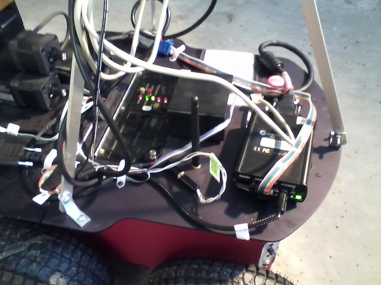
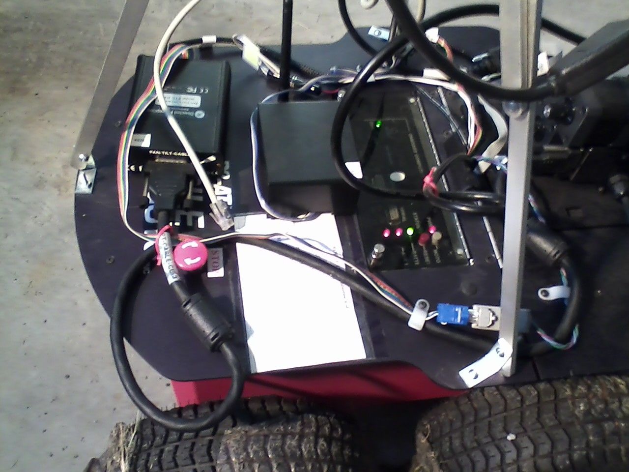
- Complete system and closeup of Tripod
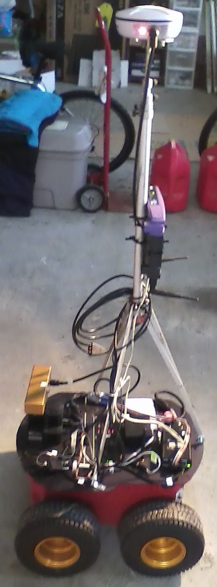
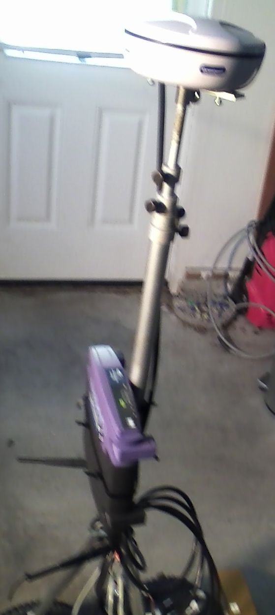
Software
The GPS was tested using the serialGPS object. The source files for this homegrown GPS interface are serialGPS.cpp/.h. See the software section for more details on this. -- DamianLyons - 2011-07-11Rotational Legged Locomotion

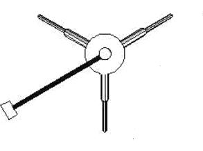
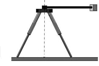 The Rotopod is a novel robot mechanism which combines the features of wheeled and legged locomotion in an unusual way.
This robot has the advantage of legged locomotion in stepping its 1-DOF legs over objects, but its drive mechanism is a rotating reaction mass that rotates the robot, in a controllable fashion, around each of its legs, similar to a rotating wheel. The mechanism has the potential to transfer the energy from the rotating reaction mass in an efficient manner to the legs, effecting a spinning forward motion.
When all legs are fully extended and the center arm rotating, the robot is stationary. When the length of one or more of the legs is reduced an approporiate amount, the robot may then rotate around one of its legs in contact with the ground. This 'stepping' will continue as long as the legs are maintained at these lengths.
Rotopod paper:
CLAWAR2007: 10th International Conference on Climbing and Walking Robots 16-18 July, 2007 Singapore. Lyons07_A4.pdf.
The Rotopod is a novel robot mechanism which combines the features of wheeled and legged locomotion in an unusual way.
This robot has the advantage of legged locomotion in stepping its 1-DOF legs over objects, but its drive mechanism is a rotating reaction mass that rotates the robot, in a controllable fashion, around each of its legs, similar to a rotating wheel. The mechanism has the potential to transfer the energy from the rotating reaction mass in an efficient manner to the legs, effecting a spinning forward motion.
When all legs are fully extended and the center arm rotating, the robot is stationary. When the length of one or more of the legs is reduced an approporiate amount, the robot may then rotate around one of its legs in contact with the ground. This 'stepping' will continue as long as the legs are maintained at these lengths.
Rotopod paper:
CLAWAR2007: 10th International Conference on Climbing and Walking Robots 16-18 July, 2007 Singapore. Lyons07_A4.pdf.
Videos
- Set ALLOWTOPICCHANGE = FRCVRoboticsGroup
Permissions
Persons/group who can view/change the page- Set ALLOWTOPICCHANGE = FRCVRoboticsGroup

Ideas, requests, problems regarding TWiki? Send feedback